background image

5

von 70

 Instruction handbook Mains filters 

BFN

Document No.: 5.09010.03 

1

G

ENERAL

 I

NFORMATION

1.1

Information on this Handbook

This Handbook provides important information on handling the device. A prerequisite for 
safe work is compliance with all specified safety notes and procedural instructions.

Additionally, the valid accident prevention regulations and general safety regulations ap-
plicable to the scope of application the device must be complied with.

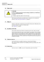
Read this Handbook, particularly the safety notes chapter, completely before beginning 
any work on the device. This Instruction handbook is part of the product and must be kept 
accessible to personnel at all times in the immediate vicinity of the device.

Summary of Contents for BFN 3-1 Series

Page 1: ...ion handbook Read the Instruction handbook before starting Language English Translation Document No 5 09010 03 Part No 442335 Version 1 Mar 2018 Mains filters BFN 3 1 Filters for mains applications E 5 09010 03 ...

Page 2: ... comments so that we can take them into account and include them when transitioning from the preliminary information to the final information as reviewed by Baumüller The conditions stipulated in the following section under Obligatory are invalid in case of pre liminary information Obligatory This Instruction handbook is a part of the equipment machine This Instruction handbook must be available t...

Page 3: ...l protective equipment 11 2 7 Special hazards 12 2 8 Fire fighting 13 2 9 Safety equipment 13 2 10 Behavior in case of danger or accidents 13 2 11 Signs and labels 14 3 Technical Data 15 3 1 Operating conditions 15 3 1 1 System types 15 3 1 2 Requirements to the energy supply power supply 16 3 1 3 Required environmental conditions 17 3 2 Dimensions 18 3 2 1 Baumüller filters for TN TT systems 18 3...

Page 4: ...nds on the electrical mains 47 7 3 Demands on the connection cable 47 7 4 Grounding conductor connection and RCD compatibility 48 7 5 System requirements with regard to EMC stability 48 7 5 1 General information about converters 48 7 5 2 Measures taken to assure EMC 49 7 6 Procedure of the installation 54 7 7 Connection diagram 55 8 Maintenance 57 8 1 Safety notes 57 8 2 Environmental conditions 5...

Page 5: ...ed safety notes and procedural instructions Additionally the valid accident prevention regulations and general safety regulations ap plicable to the scope of application the device must be complied with Read this Handbook particularly the safety notes chapter completely before beginning any work on the device This Instruction handbook is part of the product and must be kept accessible to personnel...

Page 6: ... personal injury and material damage Recommendations DANGER points out an immediately dangerous situation that will lead to severe injuries or death if not avoided WARNING points out a potentially dangerous situation that could lead to severe injuries or death if not avoided ATTENTION points out a potentially dangerous situation that could lead to minor or slight inju ries if not avoided NOTICE po...

Page 7: ...vant gov ernmental or local regulations concerning the dimensioning and protection of conductors grounding disconnectors overcurrent protection etc The person who carried out the mounting or installation is liable for any damage incurred when assembling or connecting the device 1 4 Copyright protection The Instruction Handbook must be treated confidentially It is to be used exclusively by personne...

Page 8: ...nly be operated in accordance with the stipulated methods procedures and conditions Anything else not presented here including the op eration of devices in mounted positions is not permitted and must be cleared with the plant on a case by case basis If the devices are operated in any other manner than as described within these Instruction Handbook then all guarantee and warranty rights are rendere...

Page 9: ...facturer 2 2 Changes and modifications to the device n order to prevent hazards and to ensure optimum performance no changes additions or modifications may be undertaken on the device that have not been explicitly approved by the manufacturer 2 3 Proper usage m Observe all specifications of the Instruction Handbook m When configuring ensure that the device is always operated within its specifica t...

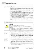
Page 10: ...n dition 2 5 Personnel training m Certain activities can only be performed by the persons stated in the respective chapters of these Instruction Handbook In this Instruction Handbook the following qualifications are stipulated for various areas of activity Operating personnel n The drive system may only be operated by persons who have been specially trained familiarized and authorized n Troublesho...

Page 11: ...n each working area must be observed Wear for special work Protective work clothing must be snug fitting work clothes with low tearing resistance narrow sleeves and with no extending parts Wear hair net No rings or necklaces Hard hat Protects against objects falling down and flying around objects Safety shoes Protects against heavy objects falling down Protective gloves Protects hands against fric...

Page 12: ... components can be life threatening Therefore m Switch off the power supply immediately in case of damage to the power supply insulation m Only allow work on the electrical system to be performed by qualified personnel m Switch off the current when any kind of work is being performed on the electrical system and ensure safety before switching on again m The device must be operated in a control cab...

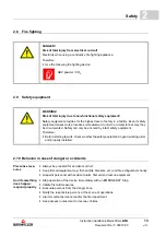
Page 13: ...ger zone m Notify the responsible persons at the scene of operations m Alarm medical personnel and or the fire department m Keep access routes clear for rescue vehicles DANGER Risk of fatal injury from electrical current Electricity when using a conductive fire fighting appliance Therefore m Use the following fire fighting device ABC powder CO2 WARNING Risk of fatal injury due to non functional sa...

Page 14: ...o illegible symbols Over the course of time stickers and symbols on the device can become dirty or oth erwise unrecognizable Therefore m Maintain all safety warning and operating labels on the device in easily readable condition Electrical voltage Only qualified personnel may work in the marked workspace Unauthorized persons may not touch the marked working materials DANGER Risk of injury due to h...

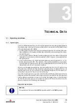
Page 15: ...rts PE The cabinets of the electrical installation are grounded The separation is reached by the use of an isolating transformer or with the use of an independent current source generator battery If there is an adequate low impedance grounding within the TN or the TT system then a line side fuse is activated A high impedance grounding does not activate the fuse so that the ground currents error cu...

Page 16: ...point IT system Industrial system with a direct or low impedance grounded junction of phases grounded delta wye Rated input supply voltage frequency UAC 3 x 400 V 50 60 Hz 3 x 480 V 50 60 Hz Absolute input supply voltage UAC max 3 x 528 V 50 60 Hz Absolute frequency maximum 63 Hz Harmonic frequencies mains voltage EN 61800 3 chapter 5 2 2 1 table 2 THDU b 10 Mains voltage asymmetry EN 61000 2 4 ta...

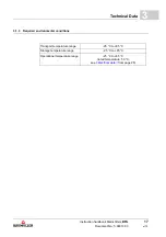
Page 17: ... Document No 5 09010 03 17 of 70 3 3 1 3 Required environmental conditions Transport temperature range 25 C to 85 C Storage temperature range 25 C to 85 C Operational temperature range 25 C to 85 C rated temperature 50 C see ZElectrical data from page 28 ...

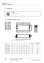
Page 18: ... D E F L G H PE connection Connection mm2 flex rigid BFN 3 1 0007 001 190 40 70 20 180 160 185 5 4 M5 4 6 BFN 3 1 0016 001 250 50 70 25 235 220 245 5 4 M5 4 6 BFN 3 1 0030 001 270 50 85 30 255 240 265 5 4 M5 10 16 BFN 3 1 0042 001 310 50 85 30 295 280 305 5 4 M5 10 16 BFN 3 1 0056 001 250 85 90 60 235 220 258 5 4 M6 16 25 BFN 3 1 0075 001 270 80 135 60 255 240 278 6 5 M6 25 35 BFN 3 1 0100 001 270...

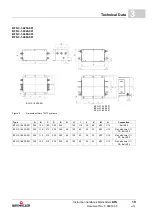
Page 19: ...1 Figure 2 Dimensions filters TN TT systems Type A B C D E G H I J K M N Connection BFN 3 1 0250 001 300 125 180 205 230 120 110 40 62 M10 12 Bolt M10 BFN 3 1 0320 001 300 115 210 235 260 40 120 60 35 20 M12 12 Rail with hole 11 PE Bolt M12 BFN 3 1 0400 001 300 115 210 235 260 40 120 60 35 20 M12 12 Rail with hole 11 PE Bolt M12 BFN 3 1 0600 001 300 135 210 235 260 40 120 60 35 20 M12 12 Rail with...

Page 20: ... 3 1 320 001 BFN 3 1 400 001 BFN 3 1 600 001 Figure 3 Dimensions filters TN TT systems Type A B C D E G H I J K M N Connection BFN 3 1 0320 101 300 116 210 235 260 42 120 120 36 30 M10 12 Rail with hole 11 PE Bolt M10 BFN 3 1 0400 101 300 116 210 235 260 42 120 120 36 30 M10 12 Rail with hole 11 PE Bolt M10 BFN 3 1 0600 101 300 116 210 235 260 42 145 120 36 30 M10 12 Rail with hole 11 PE Bolt M10 ...

Page 21: ... Mains filters BFN Document No 5 09010 03 21 of 70 3 BFN 3 1 1000 101 Figure 4 Dimensions filters TN TT systems Type A B C D E G H I J K M N Connection BFN 3 1 1000 101 350 166 250 275 300 65 290 160 61 40 M12 12 Rail with hole 14 PE M12 ...

Page 22: ...84143A0150R410 PE M10 x 38 Tightening torque 10 1mm PE M10 x 38 Tightening torque 10 1mm Terminals 95mm2 Tightening torque 15 20Nm Terminals 95mm2 Tightening torque 15 20Nm Marking Load Line Figure 5 Dimensions filters TN TT systems EPCOS for BM5174 NOTE Only for active mains inverter BM5174 Type Connection EPCOS B84143A0150R410 Terminals 95 mm PE Bolt M10 ...

Page 23: ...150 40 Figure 6 Dimensions filters TN TT system Schaffner for BM4135 BM4145 NOTE FN 3120H 80 35 for active mains inverter BM4135 FN 3120H 150 40 for active mains inverter BM4145 Type A B C D E F G H I J K L FN 3120H 80 35 221 169 140 140 115 155 6 5 1 45 M10 18 55 FN 3120H 150 40 221 169 140 140 115 155 6 5 1 51 M10 13 62 ...

Page 24: ...berg GmbH 24 of 70 3 2 Schaffner FN 3100 300 99 Figure 7 Dimensions filters TN TT system Schaffner for BM4163 Type W X Y Z FN 3100 300 99 71 5 22 M12 105 NOTE FN 3100 300 99 for active mains inverter BM4163 Type A B C D E F G H I J L FN 3100 300 99 440 200 200 400 420 160 8 1 5 105 M12 70 ...

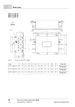
Page 25: ...002 Abbildung 8 Dimensions filters IT systems Type A B C D E G H I J K M N Anschluss BFN 3 1 0150 002 300 120 160 185 210 120 55 M10 12 Bolt M10 BFN 3 1 0250 002 300 125 180 205 230 120 110 40 62 M10 12 Bolt M10 BFN 3 1 0320 002 300 115 210 235 260 40 120 60 35 20 M12 12 Rail with hole 11 PE Bolt M12 BFN 3 1 0400 002 300 115 210 235 260 40 120 60 35 20 M12 12 Rail with hole 11 PE Bolt M12 BFN 3 1 ...

Page 26: ...3 1 320 001 BFN 3 1 400 001 BFN 3 1 600 001 Figure 9 Dimensions filters IT systems EPCOS Type A B C D E G H I J K M N Connection BFN 3 1 0320 102 300 116 210 235 260 42 120 120 36 30 M10 12 Rail with hole 11 PE Bolt M10 BFN 3 1 0400 102 300 116 210 235 260 42 120 120 36 30 M10 12 Rail with hole 11 PE Bolt M10 BFN 3 1 0600 102 300 116 210 235 260 42 145 120 36 30 M10 12 Rail with hole 11 PE Bolt M1...

Page 27: ...4 0 kg BFN 3 1 0130 001 4 2 kg BFN 3 1 0180 001 6 0 kg EPCOS B84143A0150R410 1 13 5 kg Schaffner FN 3120H 80 35 1 5 0 kg Schaffner FN 3120H 150 40 1 6 3 kg Schaffner FN 3100 300 99 1 11 8 kg BFN 3 1 0150 002 6 0 kg BFN 3 1 0250 001 BFN 3 1 0250 002 15 kg BFN 3 1 0320 001 BFN 3 1 0320 002 21 kg BFN 3 1 0400 001 BFN 3 1 0400 002 21 kg BFN 3 1 0600 001 BFN 3 1 0600 002 22 kg BFN 3 1 0320 101 BFN 3 1 ...

Page 28: ...fore m The cross section of the protective conductor must be at least 10 mm2 EN 61800 5 1 chap 4 3 5 5 2 NOTE Rated current of used filters must be greater or the same with the RMS values of the actual mains current actual mains current RMS value of the mains current during the total cycle time of the drive The RMS value is calculated at short time operation S3 as follows Ieff 1 T i 2 0 T dt ...

Page 29: ...net 2125 VDC 2 s Connection L1 L2 L3 safe to touch screw contact PE Connection Bolt M5 M6 M10 Maximum connection cross sec tion 4 mm2 4 mm2 10 mm2 10 mm2 16 mm2 25 mm2 50 mm2 50 mm2 50 mm2 Power loss typical 4 W 8 W 12 W 15 W 18 W 24 W 24 W 30 W 35 W Protection class IP 20 EPCOS B84143A0150R410 Max supply voltage 3 x 480 VAC 10 50 60 Hz Rated current at TB 50 C 150 A Peak current at TB 50 C 1 5 x ...

Page 30: ... 1 5 x IN for 1 min per hour 1 5 x IN for 1 min per hour 1 5 x IN for 1 min per hour Test voltage Cable Cable 2250 VDC 2 s Cable Cabinet 2750 VDC 2 s Connection L1 L2 L3 safe to touch screw contact PE Bolt M10 L1 L2 L3 safe to touch screw contact PE Bolt M10 L1 L2 L3 safe to touch screw contact PE Bolt M12 Maximum connection cross section 50 mm2 95 mm2 150 mm2 Protection class IP 20 IP 20 IP 20 El...

Page 31: ...l 60 W 40 W 50 W 65 W Protection class IP 00 BFN 3 1 101 0320 0400 0600 1000 Max supply voltage 3 x 480 VAC 10 50 60 Hz Rated current at TB 50 C 250 A 320 A 400 A 1000 A Peak current at TB 50 C 1 5 x IN for 3 min per hour or 2 5 x IN for 30 s per hour Test voltage Cable Cable 2280 VDC 2 s Cable Cabinet 2690 VDC 2 s Connection Rail with hole 11mm PE Bolt M10 Rail with hole 14mm PE Bolt M12 Power lo...

Page 32: ...inet 2700 VDC 2 s Connection Bolt M10 Rail with hole 11mm PE Bolt M12 Rail with hole 11mm PE Bolt M12 Rail with hole 11mm PE Bolt M12 Power loss typical 30 W 60 W 40 W 50 W 65 W Protection class IP 00 BFN 3 1 102 0320 0400 0600 1000 Max power supply 3 x 480 VAC 10 50 60 Hz Rated current at TB 50 C 250 A 320 A 400 A 1000 A Peak current at TB 50 C 1 5 x IN for 3 min per hour or 2 5 x IN for 30 s per...

Page 33: ...ters combined with Baumüller converters Baumüller motor cables and Baumüller motors If all installation and EMC notes of this Handbook are complied with it is assumed that the interference suppressed drive accords to the protection requirements of the EMC Directive 89 336 EWG and of the EMC act EMVG NOTICE m The mains filters may not be used as a motor filter at the converter output m Mains filter...

Page 34: ...ustrial distribution system of high impedance can cause a safety risk No limit values can be defined at IT systems which are used for complex industrial systems EN 61800 3 chapter 6 3 2 3 b NOTE An error case motor ground connection can lead to overload and perhaps destruc tion of the mains filters The use of mains filters BFN 3 1 XXX X02 is possible but it is not recommended to apply mains filter...

Page 35: ...on Handbook of the power converter the protection requirements of the European EMC Directive and of the EMC Act EMVG accordant to 3 sec 1 are fulfilled NOTE The emission of radio interferences is to a high level dependent of the wiring the vol ume expansion and the arrangement of the components in the installation This is why the ensuring of the EMC according to the legal regulations only is possi...

Page 36: ...y Load Figure 10 Block diagram WARNING Filters cause high discharge currents and are incompatible if they have RCDs The notes of EN 50178 must be considered when configuring Due to the high discharge currents the cross section of the ground conductors at the filter must be at least 10 mm2 EN 50178 chapter 5 3 2 1 The grounding conductor must be connected to the filter before commissioning NOTE In ...

Page 37: ...Description of the devices Instruction handbook Mains filters BFN Document No 5 09010 03 37 of 70 4 4 2 Type plate Type code Rated current Figure 11 Type plate 4 3 Type code Figure 12 Type code ...

Page 38: ...Type code Instruction handbook Mains filters BFN Document No 5 09010 03 Baumüller Nürnberg GmbH 38 of 70 4 3 ...

Page 39: ...perature range 25 C to 85 C NOTICE Damage due to unauthorized transport Transport handled by untrained personnel can lead to a substantial amount of mate rial damage Therefore m The unloading of the packages upon delivery as well as the in house transport should only be done by trained personnel m Contact Baumüller Nürnberg GmbH sales office if necessary WARNING Danger of physical impact Secure de...

Page 40: ...sible representative of Baumüller Nürnberg Gm bH 5 4 Unpacking After having received the packaged device h Avoid forceful transport agitation and hard jolts e g when putting an item down If no transport damage is visible h Open the packaging of the device h Verify the delivery scope based on the delivery note File a claim with the responsible Baumüller representative if the delivery is incomplete ...

Page 41: ...s a result of faulty mounting The mounting requires qualified personnel with adequate experience Faulty mount ing can lead to life threatening situations or substantial material damage Therefore m Only allow mounting to be performed by employees of the manufacturer or by oth er qualified personnel WARNING Danger of mechanical impact Secure devices against falling down Therefore m Take suitable mea...

Page 42: ...ection cable must be screened at lengths 30 cm The screen must be grounded on both sides m The input and output cables of the filters must spatially be divided at least 30 cm m Connect the filter cabinet bonded face to face to ground m The mains filters BFN can be used for global clearance of the installation In this case it must be placed directly at the mains supply position on the same mounting...

Page 43: ...uction Carry out mounting as follows 1 Provide suitable transport lifting equipment as required 2 Keep suitable fastening components available 3 Mount device CAUTION Eye injury due to catapulting particles Metal particles are catapulted when making the drill holes and the cutout sections Therefore Wear protective eye wear ...

Page 44: ...Mounting instruction Instruction handbook Mains filters BFN Document No 5 09010 03 Baumüller Nürnberg GmbH 44 of 70 6 3 ...

Page 45: ...alified personnel are persons who on account of their occupational training ex perience instruction and knowledge of relevant standards and stipulations accident prevention regulations and operating conditions are authorized by the persons re sponsible for the safety of the facilities to perform the respective activities that are necessary Qualified personnel must recognize and prevent potential r...

Page 46: ...d after operation of this filter the parts carry dangerous voltage DANGER Danger to life from electrical current Connection cross section grounding conductor at least 10 mm2 EN 50178 chapter 5 3 2 1 DANGER Danger to life from electrical current Stored electrical charge Therefore m Observe the discharge time of the capacitors and do not touch parts under tension m Observe the notes on the connected...

Page 47: ...mandatorily required for operation of the device h Use copper cable approved for a minimum of 60 C drives 3 x 100 A or 75 C drives 3 x 100 A if UL 508C is observed DANGER Risk of fatal injury from electrical current If the requirements for the electrical mains are not complied the device can be dam aged or destroyed Thereby persons can be greatly endangered Therefore m Prior to installation ensure...

Page 48: ...ures The following causes are the reason for interferences in the drive system m Capacitive discharge currents Here is a great rate of rise of voltages when switching semiconductors m Great currents and rate of rise of voltages in the motor cables The interference energy which is bounded into magnetic fields reaches frequencies of a few hertz to about 30 MHz Due to the great rate of rise of voltag...

Page 49: ...iation out side the power converter If the screening attenuation of the control cabinet is high enough see limit values of the interference emission complying with EMVG for your system and if the EMC compatibility in the internal space is ensured this can be as sumed if the configuration notes of this chapter are complied with the control cables can be mounted unscreened Power choke Consider the i...

Page 50: ...imited The length is dependent of the cross section of the cable for example 100 m at 1 5 mm2 30 m at 35 mm2 The max imum length should be reduced by the factor 1 n if n parallel connected motor cables are used m The screened motor cable between the power converter and the motor must be one piece The cable may not be interrupted by terminals contactors fuses etc m The smallest possible effective h...

Page 51: ...ing does not comply to EMC A reference surface is required to connect the devices large surfaced with the potential to ground for example a metallic bright mounting plate and cabinet parts m Mount the power converter with its mains filters and the bonded face to face screen contactor of the motor cable to the same reference surface m All grounding conductors and screens should be led directly abov...

Page 52: ... electromagnetic fields Thereby it does not matter if it is an electric or a magnetic field Here screening must be made on both sides Figure 17 Cable installation apply screen m Applying the screen to ground on both sides achieves that the cable remains in the screening system cabinet m The both sided grounding of cable screenings nearly excludes an influence due to ground loops potential differen...

Page 53: ...reening effect with errors in the MHz range up to 30 dB Figure 18 Proposal for a screening connection NOTE The braided screen must have a coverage of at least 85 The following lines possess an especially high interference potential m Motor cable m Cable to external chopper resistors m Cable between mains filter and power choke m Cable between power choke and converter Available screening terminals...

Page 54: ...e cross section of the grounding conductor must be greater than 10 mm2 NOTE Installation notes m Don t connect mains filters in parallel m Don t connect mains filters of the same type in series the attenuation character istics will not be approved m Connect the PE terminal on the load side of the filter with low impedance to the mounting board Ideal is a zinc plated L bracket or with a HF earth st...

Page 55: ... 5 09010 03 55 of 70 7 7 7 Connection diagram Figure 19 Filter connection Connection notes Power choke if required Power converter Main contactor 1L1 1L2 1L3 PE 2L1 2L2 2L3 Cross section system connection compliant to EN 60204 1 Installation of cables see EMC notes ...

Page 56: ...Connection diagram Instruction handbook Mains filters BFN Document No 5 09010 03 Baumüller Nürnberg GmbH 56 of 70 7 7 ...

Page 57: ...e device that could be dangerous during the mainte nance m Pay heed to areas that could still be electrically energized after operation WARNING Risk of injury due to improperly performed maintenance work Improper maintenance can lead to severe personal injury and material damage Therefore m Before beginning work make sure that there is enough space for mounting m Make sure that the mounting area i...

Page 58: ... specified environmental conditions are complied with Information referring to the environmental conditions see ZRequired environmental conditions on page 17 8 3 Repairs In case of device damage please inform your sales office or Baumüller Nürnberg GmbH Ostendstr 80 90 90482 Nürnberg Deutschland Tel 49 9 11 54 32 0 Fax 49 9 11 54 32 1 30 E Mail mail baumueller de Internet www baumueller de ...

Page 59: ...act units Irated AC 50 C TN TT system Part No 7 A BFN 3 1 0007 001 314277 16 A BFN 3 1 0016 001 314278 30 A BFN 3 1 0030 001 314279 42 A BFN 3 1 0042 001 314280 56 A BFN 3 1 0056 001 314281 75 A BFN 3 1 0075 001 314282 100 A BFN 3 1 0100 001 314283 130 A BFN 3 1 0130 001 314284 180 A BFN 3 1 0180 001 314285 250 A BFN 3 1 0250 001 373891 320 A BFN 3 1 0320 001 1 439384 BFN 3 1 0320 101 373896 400 A...

Page 60: ...N 3120H 80 35 for BM4135 417872 125 A Schaffner FN 3120H 150 40 for BM4145 416405 300 A Schaffner FN 3100 300 99 for BM4163 418234 for mains inverter compact units 1 available on request Irated AC 50 C IT system Part No 150 A BFN 3 1 0150 002 433177 250 A BFN 3 1 250 002 373620 320 A BFN 3 1 320 002 373894 BFN 3 1 320 102 1 439386 400 A BFN 3 1 400 002 373898 BFN 3 1 400 102 1 439387 600 A BFN 3 1...

Page 61: ...struction handbook Mains filters BFN Document No 5 09010 03 61 of 70 9 9 2 Screening terminals Abbildung 20 Screening terminals for grounding Cable diameter mm Part No 2 x 2 6 mm 226752 3 8 mm 226741 4 13 5 mm 226745 10 20 mm 226749 ...

Page 62: ...Screening terminals Instruction handbook Mains filters BFN Document No 5 09010 03 Baumüller Nürnberg GmbH 62 of 70 9 2 ...

Page 63: ...compliance with the health and safety regulations m Take heed of any special local regulations If you are unable to directly ensure safe disposal yourself commission a suitable disposal contractor m In the event of a fire hazardous substances could possibly be generated or re leased m Do not expose electronic components to high temperatures m Beryllium oxide is used as inner insulation for example...

Page 64: ...licies of your com pany as well as with all national regulations of the responsible disposal facilities and au thorities In case of doubt consult the bureau of commerce or environmental protection authority responsible for your company WARNING Danger due to faulty disassembly Demounting and disposal requires qualified personnel with adequate experience Therefore m Only allow disassembly and dispos...

Page 65: ...r 48 Guarantee provisions 8 H Hard hat 11 I Installation procedure 54 Instruction handbook Contents of 9 K Key to symbols 6 L Limitation of liability 7 List of figures 67 M Mains supply 16 Maintenance 57 Modifications 9 N Note 6 O Operating conditions 15 Operating personnel 10 Operator Responsibility 10 P Personnel Operating 10 Personnel Qualified 10 Protection eyewear 11 Protective equipment 11 P...

Page 66: ...Instruction handbook Filter for mains applications Document No 5 09010 03 Baumüller Nürnberg GmbH 66 of 70 Index ...

Page 67: ...M5174 22 Dimensions filters TN TT system Schaffner for BM4135 BM4145 23 Dimensions filters TN TT system Schaffner for BM4163 24 Dimensions filters IT systems 25 Dimensions filters IT systems EPCOS 26 Block diagram 36 Type plate 37 Type code 37 Cabling power unit 49 Cable installation effective height 50 Cable installation loop area 50 Cable installation cabinet outlet 52 Cable installation apply s...

Page 68: ...Instruction handbook Filter for mains applications Document No 5 09010 03 Baumüller Nürnberg GmbH 68 of 70 List of Figures ...

Page 69: ...ok Mains filters BFN Document No 5 09010 03 69 of 70 Overview of Revisions Overview of Revisions Version Edition Changes 5 09010 01 03 Dec 2012 First edition 5 09010 02 20 Apr 2017 Revision 5 09010 03 1 Mar 2018 Revision ...

Page 70: ...Instruction handbook Mains filters BFN Document No 5 09010 03 Baumüller Nürnberg GmbH 70 of 70 Notes ...

Page 71: ......

Page 72: ...erungsdienst aktualisiert Bitte beachten Sie dass Angaben Zahlen Informationen aktuelle Werte zum Druckdatum sind Zur Ausmessung Berechnung und Kalkulationen sind diese Angaben nicht rechtlich verbindlich Bevor Sie in dieser Betriebsanleitung aufgeführte Informationen zur Grundlage eigener Berechnungen und oder Verwendungen machen informieren Sie sich bitte ob Sie den aktuellsten Stand der Informa...

Reviews: