background image

Installation

Accessories

38


BUG 3/2/20 Basic Feed Unit

5.96064.02

Baumüller Nürnberg GmbH

Connection

To intermediate circuits ZK+ and ZK-

  with short 10-mm² wires for Series 2/20 type

  with short 4-mm² wires for Series 3 type

deenergized.

Dimensions

Summary of Contents for BUG 2

Page 1: ...PÓŁKA JAWNA Jana Dlugosza 2 6 Street 51 162 Wrocław Poland biuro rgbelektronika pl 48 71 325 15 05 www rgbautomatyka pl www rgbelektronika pl DATASHEET www rgbautomatyka pl www rgbelektronika pl OTHER SYMBOLS BUG2 60 31 B 010 BAUMÜLLER ...

Page 2: ...ed with a wide variety of tools and having several testing stands at their disposal are a guarantee of the highest quality service OUR SERVICES ENCODERS SERVO DRIVERS LINEAR ENCODERS SERVO AMPLIFIERS CNC MACHINES MOTORS POWER SUPPLIERS OPERATOR PANELS CNC CONTROLS INDUSTRIAL COMPUTERS PLC SYSTEMS Repair this product with RGB ELEKTRONIKA ORDER A DIAGNOSIS Buy this product at RGB AUTOMATYKA BUY ...

Page 3: ...BAUMÜLLER Technical description and operation manual Edition 15 February 2002 BASIC FEED UNIT BUG 3 2 20 E 5 96064 02 ...

Page 4: ...be been adhered to there will be no personal danger during the installation and commissioning stages The commisioning is prohibited until it has been positively determined that the machine into which these components are to be incorporated complies with EC machine regulations This technical description replaces and nullifies all provious description In order to provide the best possible service we...

Page 5: ...tion Unpacking 11 4 Assembly 13 4 1 Dimensions 14 4 2 Assembly Information 16 5 Installation 17 5 1 Danger Information 17 5 2 EMC Information 18 5 3 Connection Diagram 24 5 3 1 BUG 2 25 5 3 2 BUG 3 24 5 3 3 BUG 20 26 5 3 4 Connection Information 27 5 4 Pin Assignments 28 5 4 1 Power Terminals 28 5 4 2 Control Terminals 28 5 5 Accessories 29 5 5 1 Transformers 29 5 5 2 Starting Current Limitation D...

Page 6: ...Commissioning 41 6 1 Function Plan 44 6 2 Messages and Warnings 46 6 3 Test Connector 48 7 Maintenance 49 7 1 Maintenance Information 49 7 2 Disposal 50 8 Appendix 51 8 1 Manufacturer Declaration 51 8 2 Declaration of Conformity 52 8 3 Conditions of Business and Delivery 53 8 4 Index 54 ...

Page 7: ...d Feed back Unit BUG Baumotronic Converter Basic Feed Unit BUM Baumotronic Converter Mono Power Unit BUS Baumotronic Converter Servo Power Unit DC Direct current DIN German Standardization Institute Deutsches Institut für Normung e V EMC Electromagnetic compatibility EN European standard HS Main contactor IPM Intelligent Power Module MSL Mean sea level PE Protective earth SM Synchronous motor ZK I...

Page 8: ...Abbreviations IV BUG 3 2 20 Basic Feed Unit 5 96064 02 Baumüller Nürnberg GmbH ...

Page 9: ...eventing accidental contact at commissioning and in the case of casual use of control elements located close to the equipment DIN VDE 0106 Part 100 Accident Prevention Regulation VBG4 Electrical Systems and Equipment At routine testing of this equipment a high voltage test is carried out that conforms with preliminary standard EN 50178 VDE 0160 11 94 Section 9 4 5 The protective measures and safet...

Page 10: ...information below is for your own personal safety and on the other to prevent damage to the described products or to other connected equipment In the context of the operating instructions and the information on the products themselves the terms used have the following meanings DANGER This means that death severe personal injury or damage to property will occur unless appropriate safety measures ar...

Page 11: ... safety standards Trained or instructed in accordance with recognized safety standards in the care and use of appropri ate safety equipment Appropriate Use WARNING You may only use the equipment system for the purposes specified in the operating instructions and in conjunction with the third party equipment and components recommended or authorized by BAUMÜLLER NÜRNBERG GmbH For safety reasons you ...

Page 12: ...Safety Information 4 BUG 3 2 20 Basic Feed Unit 5 96064 02 Baumüller Nürnberg GmbH ...

Page 13: ...it the BUS servo power unit The BUG 2 3 20 named basis feed units are mains side power converters for feeding the BUS 3 21 20 drive amplifiers They have a ballast circuit to dissipate the drive s breaking energy They are available with internal ballast resistor or as E version with a connector for external resistors Features BUG 3 basic unit for up to 10 5 kW BUG 2 basic unit for up to 18 kW BUG 2...

Page 14: ...n the input side This device is shunted out after the start up stage Power Supply The internal switching power supply generates the supply voltages for the connected servo units from the intermediate circuit or from an external auxiliary voltage In addition permanent monitoring is carried out of the temperature the intermediate circuit voltage the supply voltages and the ballast function In the ca...

Page 15: ... Error memory Ballast resistor overloading TB Ballast ON for t 1 5 s Intermediate voltage Uzk too high 400 V 15 V controller supply not OK 12 5 V Temperature of heatsink TKK is too high External ballast option Ballast resistor Ballast control Uzk 375 V Uzk 400 V Intermediate circuit monitoring Switching power supply 15 V 24 V SELV X9 Controller supply and communications Ready for use Green Ready f...

Page 16: ... potential free Isolation transformer T2 1900 7153 1900 7176 Ballast resistor RB peak power for t 1 5 s peak power for t 1 8 s internal version B external version E rated power 9 kW 16 Ω 190 W 16 Ω As required 15 kW 9 4 Ω 400 W 8 Ω As required 37 kW 4 Ω 900 W 4 Ω As required Power loss in rated operation without ballast 5 110 W 200 W 280 W Fan No Supplied internally Supplied internally Environment...

Page 17: ...dapter BU the isolating transformer T2 is specially matched to the mains unit transformer T2 is not needed for operating the basic units 5 Power losses of the devices on one hand this is important for rating the switching cabinet and on the other for rating the BUG basic unit Σ PV Σ Ptomotor PN BUG see also Transformer Rating 6 Coolant temperature measured 50 mm below the device according to DIN V...

Page 18: ...Technical Data Type Code 10 BUG 3 2 20 Basic Feed Unit 5 96064 02 Baumüller Nürnberg GmbH 2 3 Type Code ...

Page 19: ...hat the shipment is complete you can start assembly Cardboard cartridge paper and or wood are used as packaging materials that can be disposed of according to local regulations Report any damage in transit without delay DANGER If the unit has been damaged in transit do not connect it to the mains until appropriate high voltage testing has been carried out Ignoring this information can result in de...

Page 20: ...Transport Unpacking 12 BUG 3 2 20 Basic Feed Unit 5 96064 02 Baumüller Nürnberg GmbH ...

Page 21: ...above and below the equipment to prevent overheating The units are protected from direct contact by being installed in commercially available switching cabi nets that meet the minimum protection requirements of preliminary standard EN 50178 VDE 0160 11 94 Section 5 2 4 Plastic protectors on the devices that cover up the connections act as additional guards preventing accidental contact at commissi...

Page 22: ...Assembly Dimensions 14 BUG 3 2 20 Basic Feed Unit 5 96064 02 Baumüller Nürnberg GmbH 4 1 Dimensions ...

Page 23: ...Dimensions Assembly BUG 3 2 20 Basic Feed Unit 15 Baumüller Nürnberg GmbH 5 96064 02 Fastening Holes ...

Page 24: ...crucial to comply with the ventilation measures listed below Ignoring these measures can lead to the device overheating Ventilation must be in the specified direction from the bottom to the top Ensure that the flow of air is unobstructed There must be a minimum clearance above and below the device of 100 mm and you must ensure that there is enough cooling air that can circulate freely The temperat...

Page 25: ...ctive earth attachment The protective earth connection has to be carried out according to DIN EN 60204 VDE 0113 Part1 06 93 section 8 2 2 also pr EN 50178 VDE 0160 11 94 sections 5 3 2 and 8 3 4 or the re spective local guidelines Information about EMC correct installation as screeening earthing posi tioning of filters and running cables you will find in this document This information must be resp...

Page 26: ...omagnetic fields occur with frequencies of up to approximately 600 MHz high clock rates and fast logic circuits electromagnetic field 16 MHz 1 GHz system perturbation and harmonics caused by commutations and non sinusoidal network loading in particular with line commutated converters 100 Hz 20 kHz German EMC Law EMVG This converter complies with Paragraph 5 Section 5 Sentence 3 of the German EMC L...

Page 27: ...configuration information below Cabling To suppress radiated noise outside the converter you should screen all the connected cabling Also observe the topics in the section entitled Screening Feed Unit Mains Filter Operator Panel Lines routed via metallic conduit threads or connector housing with connected screen Screen s point of contact with mounting plate Screened Line Unscreened Line Distance o...

Page 28: ...the conductors must be at least 20 cm apart Lines of different EMC categories should only cross at an angle of 90 In the case of symmetrical signal transfer e g differential amplifier inputs for the speed specified value twist the conductors of each pair of wires together and twist the pairs of wires together The converter to ground plate earth connection should be as short as possible less than 3...

Page 29: ...cross section as possible and is less than 30 cm long Remove insulating layers such as varnish adhesives etc from the frame ground connections If nec essary use DIN 6798 serrated lock washers or similar to ensure a permanent conductive contact To prevent corrosion of frame ground connections use suitable pairs of metals electrochemical displace ment series and keep conductive electrolytes away fro...

Page 30: ...on the frame ground system However this is very rare if you carry out the measures described in the previous sections entitled Cabling and Grounding You can also make a capacitive RF connection of a screen to frame ground This prevents low frequency interference due to earth circuits Screened cables that pass through different EMC areas must not be separated at terminals since screen damping would...

Page 31: ... to the converter With lines that are more than 30 cm long you must screen the mains line between the converter and the filter frame ground on both sides Physically separate the filter s input and output lines by more than 30 cm Make a broad connection between the filter housing and frame ground Discharge Currents Due to the principle of operation parasitic capacities in the filter the mains unit ...

Page 32: ...V additional feed potential free To further servo units SELV Intermediate circuit L Intermediate circuit L ZK Option E External ballast resistor or BUR L1 T1 I L1 L2 L3 PE I I L2 L3 R2 K2 K1 F1 PE To further servo units To NC ground 1 8 7 6 5 4 3 2 1 K1 Controller enable SELV T2 RB ZK Ready 230 V pot free Ba Ba SELV Reset M 15 V 15 V 24 V ...

Page 33: ...Connection Diagram Installation BUG 3 2 20 Basic Feed Unit 25 Baumüller Nürnberg GmbH 5 96064 02 5 3 2 BUG 2 ...

Page 34: ...Installation Connection Diagram 26 BUG 3 2 20 Basic Feed Unit 5 96064 02 Baumüller Nürnberg GmbH 5 3 3 BUG 20 ...

Page 35: ...basic unit K1 Mains contactor with auxiliary contact for controller enable K2 R2 Starting current limitation prevents the B6 rectifier s permissible non repetitive peak current ION from being exceeded the contactor shunts out resistors R 10 Ω 50 W after one second this is always necessary when using capaci tor unit BUK otherwise only with transformers T1 rated at 5 kVA and above available as a com...

Page 36: ...nection of external ballast BUG 20 only L ZK Ballast Connection of external ballast BUG 3 only 5 4 2 Control Terminals Plug in connection X9 Bus connection to the servo power units Supply voltages and operating messages are routed via this connection Terminal strip X5 Pin No Assignment 1 Additional feed via isolating transformer T2 230 VAC 2 Additional feed via isolating transformer T2 230 VAC Ter...

Page 37: ...n average mean value n nmax 0 5 matched to a typical CNC feed drive When operating at rated speed n nmax 1 you must take into account the complete motor power Isolating transformer or autotransformer Autotransformers are preferable at power ratings above 5 kVA Note that the intermediate circuit may not be grounded and that potential is connected to the intermediate circuit as well as the motor If ...

Page 38: ...G 2 B U G 20 B U G 3 0 4 7154 4 7 5 0 0 0 0 4 7159 2 4 2 0 0 0 1 0 7155 4 15 0 0 0 0 1 0 7160 2 7 5 0 0 0 2 5 7156 4 22 5 0 0 0 2 5 7161 2 15 0 0 0 0 5 0 7157 4 68 0 0 0 1 5 0 7162 2 22 5 0 0 1 8 0 7158 4 77 0 0 0 1 8 0 7163 2 27 0 1 0 1 10 0 7164 2 29 0 1 0 1 15 0 2 7165 2 29 0 1 0 1 25 0 2 7167 2 78 0 1 1 1 1 Starting current limitation device 0 Not necessary 1 Operation with starting current li...

Page 39: ...19007157 5 0 360 195 305 68 0 300x130 9x14 19007158 8 0 360 210 305 77 0 300x150 9x14 Autotrans former Power kVA Length L mm Breadth W mm Height H mm Weight W kg Fastening Hole axb cxd mm 19007159 0 4 150 75 130 4 2 113x48 5 8x11 19007160 1 0 180 110 175 7 5 136x56 7 0x14 19007161 2 5 204 140 200 15 0 175x85 7 0x14 19007162 5 0 240 160 225 22 5 200x100 9 0x14 19007163 8 0 270 170 255 27 0 220x105 ...

Page 40: ... Current Limitation Device Technical Data Type Designation WSV 3 10 60 001 Resistor 3 x 10 Ω Rated Power 3 x 60 W Reclose after 2 s Max closing energy 350 Ws Max capacitance at UZKmax 340 V 6 mF Overload protection by safety circuit breaker with auxiliary switches Rated current 2 A Trip curve C Dimensions ...

Page 41: ...Accessories Installation BUG 3 2 20 Basic Feed Unit 33 Baumüller Nürnberg GmbH 5 96064 02 Connection Suggestion ...

Page 42: ...2 kW force ventilated TA 45 C mounted vertically Peak Power PV 18 kW for t 15 s PV 36 kW for t 7 s Max permissible ballast energy 270 kWs Operating environm temperature TB 0 45 C Coolant temperature range TK 0 45 C Storage temperature range 30 70 C 1 When UL508C is considered The resistor units are only to be used in connection with Baumüller appliances of BUG and BUM61 62 and 62T types Calculatio...

Page 43: ...ction 1 plan of basic unit Fan 24 VDC 0 25 A SELV Pre warning Error Overrtemperature BUR SELV 1 When UL508C is considered The resistor units are only to be used in connection with Baumüller appliances of BUG and BUM61 62 and 62T types Connections Type Code B U R 6 2 2 0 4 2 0 0 0 0 8 1 6 BAUMOTRONIC Resistor Unit Type Series Type Resistor Rated power 2 kW Version ...

Page 44: ...Installation Accessories 36 BUG 3 2 20 Basic Feed Unit 5 96064 02 Baumüller Nürnberg GmbH Dimensions ...

Page 45: ...be maintained during brief mains failures BUK external capacitor units are integrated in Type Series 6 housings and are available for intermediate circuit voltages of 310 V and 540 V Electrical Data Type BUK 622 31 20 BUK 622 54 05 Capacitance 20 mF 5 mF Rated voltage 310 VDC 540 VDC Max intermediate circuit voltage 400 VDC 800 VDC Charging current limitation by use of basic unit varies depending ...

Page 46: ...ries 38 BUG 3 2 20 Basic Feed Unit 5 96064 02 Baumüller Nürnberg GmbH Connection To intermediate circuits ZK and ZK with short 10 mm wires for Series 2 20 type with short 4 mm wires for Series 3 type deenergized Dimensions ...

Page 47: ...Feed Unit 39 Baumüller Nürnberg GmbH 5 96064 02 Type Code B U K 6 2 2 3 1 2 0 0 0 0 5 4 0 5 0 0 0 BAUMOTRONIC Condenser Unit Type Series Size Rated Voltage 310 V or 540 V Capacity 20 mF at 310 V 5 mF at 540 V Design 000 standard xxx customized ...

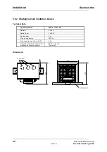
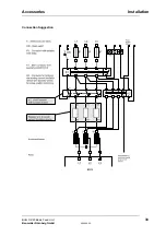
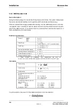
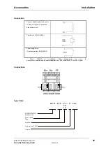
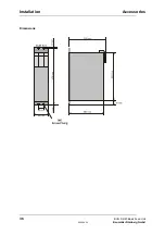
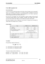
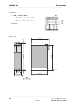
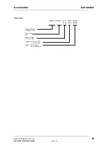
Page 48: ...Installation Accessories 40 BUG 3 2 20 Basic Feed Unit 5 96064 02 Baumüller Nürnberg GmbH ...

Page 49: ...ections on the equipment commutating reactor or the motor personal injuries are inevitable since the surfaces may carry dangerously high voltages The mains unit and the field connector of the power converter carry a dangerous voltage even when the main contactor has dropped Do not touch these modules when under power Connect test equip ment only in powerless state After the drive converter is sepa...

Page 50: ...tive parts from being touched by means of insulation the construction and arrangement of the equipment or directly mounted guards The guards in question are standard covers barriers and procedures that guarantee that people cannot touch active parts that are carrying power Switching cabinets must have an emergency off facility to switch off any voltages that could be dan gerous This does not inclu...

Page 51: ...similar Failure to do this may result in the owner being faced with consequences relating to liability legislation This is not a complete list of all the procedures necessary for safe operation of the unit If you need further information or have particular problems contact BAUMÜLLER NÜRNBERG or one of our dis tributors Observe the warning information in chapter 1 of these operating instructions NO...

Page 52: ...Commissioning Function diagram 44 BUG 3 2 20 Basic Feed Unit 5 96064 02 Baumüller Nürnberg GmbH 6 1 Function diagram ...

Page 53: ...ed on ready for use Switch on reset W202 W203 W201 L Uzk 400 V L t x Temp switch W204 L Temp 92 C BUG 2 T1 15 V 24 V Ground T2 BSs 15 V PAM U controller 1 2 3 4 6 7 8 9 10 10 V 15 V 10 V M 15 V Test adapter BU Connect via connector on the bottom of the device H1 red not connected H1 red not connected H3 red TKK temperature of power unit too high H4 red 15 V supply voltage not correct H5 red Uzk in...

Page 54: ...rature Ready for Use If no message is pending the green ready for use LED is lit and the system reports this condition to the servo units If only one message of the BUS servo units is pending and the group message on the servo units is activated in the BEDAS the system cancels ready for use and does not indi cate any further messages Intermediate Circuit If the intermediate circuit voltage exceeds...

Page 55: ...supply monitoring supervises the internal switching power supply for overloading and brief short circuits If one of these errors occurs the system generates a message and cancels ready for use Temperature Overtemperature monitoring supervises the temperature of the heatsink If this temperature ex ceeds an internally set limit value the system issues a message and cancels ready for use This message...

Page 56: ... H1 Not connected Not connected LED TKK is lit up or optocoupler output X27 4 High LED Uzk is lit up or optocoupler output X27 6 High LED T is lit up or optocoupler output X27 7 High B LED 15 V is lit up or optocoupler output X27 5 High Input recitfier overload Fan is blocked Ambient temperature too high Braking energy Pmax Ballast circuit defective or missing W xternal ballast resistor rong e Bra...

Page 57: ...remount and check safety equipment immediately after completing commissioning repair and maintenance work After carrying out any work involving intervention in the machine regardless of whether this involves the motor the actual value acquisition or the power converter the operator must carry out accep tance testing of the machine and document it chronologically in the machine log Failure to do th...

Page 58: ... heat sink Metal base plate semiconductor chip plastic housing various insulation materials PCBs on which all the open and closed loop electronics are mounted Base material Epoxy resin fibreglass woven material copper coated on both sides and plated through various electronic components such as condensors resistors relays semi conductors etc For technical reasons electronic components might need t...

Page 59: ...wing specified machine component and that its putting into operation is prohibited until the declaration is made that the machine in which this compo nent is built in complies with the regulations of the EC machine guideline 89 392 EWG appendix II B Specification of the machine component Type Basic Feed Unit BUG 3 35 31 BUG 2 60 31 BUG 20 120 31 Date Signature of the Manufacturer Nürnberg 4 März 1...

Page 60: ...hine component Type Basic Feed Unit BUG 3 35 31 BUG 2 60 31 BUG 20 120 31 Conformity of the significated product with the guidelines will be proved by following rules pr EN 50178 1994 VDE 0160 11 94 Equipment of power installation concerned electronic operating materials Nürnberg 8 January 1997 Signature of the Manufacturer Dr Ing P Kreisfeld Dipl Ing FH R A Geller Head Division Electronics CE Age...

Page 61: ...or reconfigured at the purchaser s for Baumüller as the manufacturer but without additional obligations If Baumüller ownership rights are nullified because the goods are integrated into or assem bled to other objects a portion of the ownership rights of the purchaser to that object covering the amount in question is transferred to Baumüller The purchaser keeps the property of Baumüller in custody ...

Page 62: ...er Information 2 17 Degrees of contamination 16 Discharge Currents 23 Disposal 52 E Earth circuits 21 Electrical Data 8 EMC information 18 F Filter Assembly 23 Filtering 23 G Grounding 21 I Initial Commissioning 42 Installation 17 M Maintenance 51 Manufacturer Declaration 53 N NOTE 2 P Personnel qualified 3 Power Terminals 28 S Safety information 1 Screening 22 T Technical Data 5 Temperature of co...

Reviews: