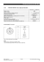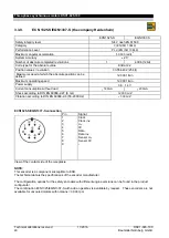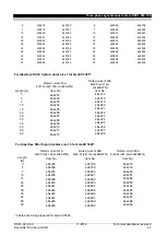
Three-phase synchronous motors DSC1-045-100
Technical alterations reserved
11/2016
DSC1-045-100
48
Baumüller Nürnberg GmbH
3.6. Motor cables
The motor cables are highly flexible trailing cables with overall shielding. They comply with VDE, UL and CSA
regulations. The control cables are integrated as star quads. The brake control and the temperature sensor are
connected via the main connector. The cables are particularly suited for the optimum use of cable racks thanks
to their small cross-section, low weight, and non-impeding surface. As a result, they can be used efficiently in
trailing chains. The overall shielding with an optical coverage of more than 85% makes the cable non-critical
from an EMC perspective.
3.6.1. Technical data
Sheath resistance to media such as coolants and machine and gearbox oils
Abrasion resistance thanks to a special surface in cable racks and trailing chains
Highly flexible trailing cable, minimum bending radius for flexible use: 12 x D
Non-blocking sheath surface with satin finish
Shield made of tinned copper braid with optical coverage of 85%
Core insulation made from TPE or polyester, sheath material: Halogen-free PUR
Cable is CFC and silicone-free
Behavior in the event of fire: Fire-inhibiting, halogen-free
Cable color RAL 1028, melon yellow
Label features Baumüller logo and VDE, UL and CSA marks
Rated voltage
Uo/U 600/1.000 V (power cores)
U 24 V DC (control cores)
Core labeling
Power cores U, VV, WWW
Colored control cable pairs as star quads in red, white, black, yellow
Assignment of pairs: (note the polarity)
Red
– black (brake)
white
– yellow (temperature)
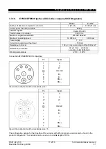
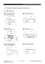
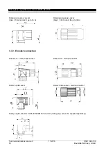
3.6.2. Main connection via connector
Note:
The connector size is determined by the standstill current I
0
of the motor used.
Motors with a standstill current of
≤ 20A feature a size 1 main connector.
For standstill currents of 20 A< I
0
≤ 36 A, a size 1.5 main connector is used.
A terminal box must be used at a I
0
> 36A.
Poles of the female main connectors:
Pin
Signal
Color/labeling
Size 1
I
0
≤ 20 A
A
B
C
D
3
4
1
1
3
4
A
B
C
D
Phase U
PE
Phase V
Phase W
B+
B-
K+
K-
U
Green/yellow
V V
W W W
Red
Black
White
Yellow
View of contact side of female connector
Summary of Contents for DSC1-045-100 Series
Page 1: ...Appli be in motion Three phase synchronous motors DSC1 045 100 ...
Page 2: ......
Page 115: ......


