Three-phase synchronous motors DSC1-045-100
DSC1-045-100
11/2016
Technical alterations reserved
Baumüller Nürnberg GmbH
49
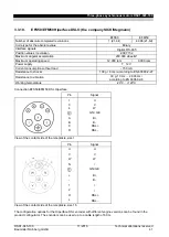
Pin
Signal
Color/labeling
Size 1.5
I
0
≤ 36 A
-
+
2
1
W
V
U
U
V
W
+
-
1
2
Phase U
Phase V
Phase W
PE
B+
B-
K-
K+
U
V V
W W W
green / yellow
Red
Black
White
Yellow
View of contact side of female connector
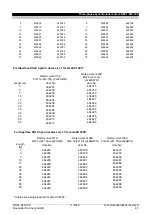
Cable cross-section
2)
Rated current
[A]
1) 2)
Connector
540 V
Size
2)
Cable diameter
2)
[mm]
4 1.5 mm
2
+
4 0.75 mm
2
15
1
11.7
– 12.3
4 2.5 mm
2
+
4 0.75 mm
2
20
1
12.7
– 14.6
4 4 mm
2
+
4 0.75 mm
2
28
1.5
14.2
– 15.4
4 6 mm
2
+
4 0.75 mm
2
36
1.5
16.6
– 17.9
4x10 mm
2
+ 4x0.75 mm
2
50
1.5
20.5
– 21.5
4x16 mm
2
+ 4x0.75 mm
2
66
-
23.0-25.8
4x25 mm
2
+ 2x(2x1.5 mm
2
)
84
-
26.3-29.7
4x35 mm
2
+ 2x(2x1.5 mm
2
)
104
-
30.8-32.5
1)
Current carrying capacity acc, to Table 5, laying type C or E VDE 0113/EN 60204 Part 1 issue 1997)
Ambient temperature 40 °C
2)
Deviating regulations apply for
approved motors
3.6.3.
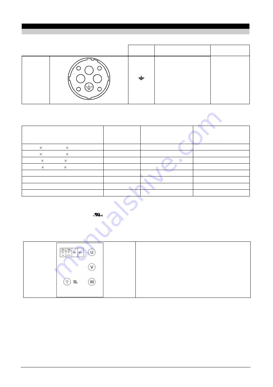
Main connection via terminal boxes
Connection diagram
U V W
Power connection
K+ / K- Temperature sensor
BD+ / BD- Brake
SL Earth wire
3.6.4. Application notes
Operating temperature
The cables can be operated within a temperature range of between -20 °C and +80 °C,
Cable laying at the motor
The cables must not touch the motor surface,
Smallest permissible bending radii
12x outer cable diameter,
Summary of Contents for DSC1-045-100 Series
Page 1: ...Appli be in motion Three phase synchronous motors DSC1 045 100 ...
Page 2: ......
Page 115: ......


