GB
- 16 -
6. Operation
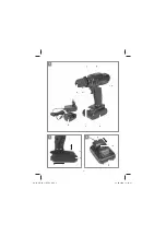
6.1 Charging the battery (Fig. 2-3)
1. Remove the battery pack (4) from the handle,
pressing the pushlock buttons (7) downwards
to do so.
2. Check that your mains voltage is the same as
that marked on the rating plate of the battery
charger. Insert the power plug of the charger
(5) into the mains socket outlet.
3. Push the charger onto the battery pack.
4. The LED (a) will be red while the battery is
being charged.
5. When charging has been completed the LED
(a) will be green.
If the battery pack fails to charge, check for the
following:
•
Voltage at the power socket
•
Good contact at the charging contacts of the
charging unit
If the battery pack still fails to charge, send
•
the charging unit
•
and the battery pack
to our customer service center.
To ensure that the battery pack provides long ser-
vice, you should take care to recharge it promptly.
You must recharge the battery pack when you
notice that the power of the cordless equipment
drops.
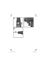
6.2 Torque setting (Fig. 4 / Item 1)
The cordless screwdriver is
fi
tted with a mechani-
cal torque selector.
The torque for a particular screw size is set with
the setting ring (1). The torque is dependent on a
number of factors:
•
On the type and hardness of the material in-
volved
•
On the type and length of the screws used
•
On the requirements that the screw connec-
tion has to satisfy
The grating disengagement of the coupling in-
dicates that the selected torque level has been
reached.
Caution! Only ever adjust the setting ring
when the equipment is at a standstill.
6.3 Drilling (Fig. 4/Item 1)
For drilling purposes, adjust the setting ring for
the torque to the last setting “Drill”. In the drill
setting the slip coupling is non-functional. The
maximum torque is available for drilling.
6.4 Changeover switch (Fig. 5/Item 2)
The slide switch above the On/O
ff
switch is for
setting the direction of rotation of the cordless
screwdriver and for preventing the cordless
screwdriver from being switched on inadvertently.
You can select between clockwise and counter-
clockwise rotation. To avoid causing damage to
the gearing, the direction of rotation must only be
changed when the screwdriver is at a standstill.
When the slide switch is in the middle position,
the On/O
ff
switch is blocked.
6.5 On/O
ff
switch (Fig. 5/Item 3)
In
fi
nitely variable speed control is possible with
the On/O
ff
switch. The further you push the
switch, the higher the speed of the cordless
screwdriver.
6.6 Battery capacity indicator (Fig. 5 /Item 10)
When you press the On/O
ff
switch, the battery ca-
pacity indicator (10) shows you the charge status
of the battery on three 3 LEDs.
All 3 LEDs are lit:
The battery is fully charged.
2 or 1 LED(s) are lit:
The battery has an adequate remaining charge.
1 LED blinks:
The battery is empty, recharge the battery.
6.7 Selector switch for 1st/2nd gear
(Fig. 4 / Item 6)
You can work with a higher or lower speed de-
pending on the position of the selector switch.
Change the gear only when the drill is at a stand-
still. If you fail to observe this point, the gearing
may be damaged.
6.8 LED lamp (Fig. 5 / Item 9)
The LED lamp (9) can be used in poor lighting
conditions to illuminate the area where you want
to drill or screw. The LED lamp (9) will be lit au-
tomatically as soon as you press the ON/OFF
switch (3).
Anl_BCD_18_Li_SPK9.indb 16
Anl_BCD_18_Li_SPK9.indb 16
12.02.2018 15:32:36
12.02.2018 15:32:36

