HBZMXSIB/10/16SD-PR-1
Page 33
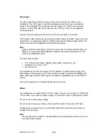
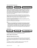
VCR Camera Switch Input (Vext)
Most time-lapse VCRs provide a hard-wired, pulse output to devices such as the
multiplexer, indicating that the VCR has just completed recording of one image of the
current camera. This lets the multiplexer know that it can switch to a new camera
input. This feature simplifies your installation since it automatically takes care of
synchronising the normal and alarm record speeds of the multiplexer with those of
the time lapse VCR. No VCR speeds then need to be set up in the multiplexer
menus, only on the VCR itself.
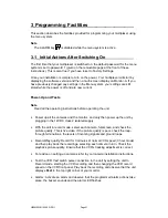
Provision is made for the VCR Camera Switch/Vext Input on the 25-way D-type
alarm connector on the rear panel of the multiplexer. An auto-detection circuit in the
multiplexer determines if this input is active, and automatically responds to it in the
RECORD mode, if the switch input detection is enabled in the menus.
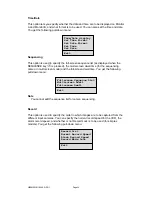
The factory default setting is ENABLED, which allows the autodetection circuit to
operate. This is the recommended setting.
An on-screen R EXT indicator replaces the Record Speed indicator while this switch
input is active and detected by the multiplexer.
Note
On power up, the autodetection circuit will wait about 15 seconds to check if the
VCR starts to output a switch pulse. The period of 15 seconds is approximately
the period between switch pulses when the VCR is running in 960 hour mode.
During this brief time, the multiplexer will not switch cameras at all, unless a switch
pulse is detected. If the switch pulse ceases, the multiplexer will also take about
15 seconds to determine that it has in fact stopped and not just changed to 960
hour mode.
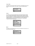
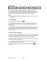
Switch Edge
The menus provide a selection for the pulse edge used for the Switch/Vext input. Do
not change this setting without first consulting Customer Support.
Monitor Outputs In Record Mode
MONITOR-A Output While Recording
On a duplex unit, you can select LIVE or PLAY mode while recording is taking place.
Hence you can select any desired Monitor-A multi-screen output on a duplex unit,
while multiplexed recording takes place on the VCR output. Monitor-A images can be
frozen.
On a simplex unit, Monitor-A only displays analogue, full-screen images while
RECORD mode is selected, and Monitor-B follows Monitor-A.
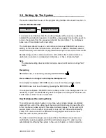
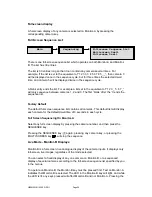
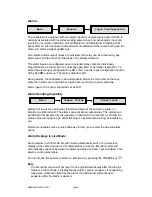
Main
VCR Setup
Switch Input
ON/OFF
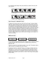
Main
VCR Setup
Switch Edge
Summary of Contents for ZMX/BD/10
Page 1: ...HBZMXSIB 10 16SD OP 1 Page 1 Operating Instructions ZMX BD 10 ZMX BS 10 ZMX CS 10 Multiplexers...
Page 3: ...HBZMXSIB 10 16SD PR 1 Page 2 This page is intentionally blank...
Page 5: ...HBZMXSIB 10 16SD PR 1 Page 4 This page is intentionally left blank...
Page 7: ...HBZMXSIB 10 16SD PR 1 Page 6 This page is intentionally left blank...
Page 78: ...HBZMXSIB 10 16SD OP 1 Page 2 This page is intentionally blank...
Page 80: ...HBZMXSIB 10 16SD OP 1 Page 4 This page is intentionally blank...


