made, however, after final installation.
11.3.1
Lighting the fire.
If closed
,
open the isolating ‘T’ connector valve. Depress the control knob and rotate it
anticlockwise to the pilot ignition position. A ‘click’ will be heard as the integral piezo
operates. A spark should be seen between the electrode and pilot tip. Turn the control
knob clockwise to the ‘Off’ position. Repeat this operation until a flame appears at the
pilot. There may be a delay before the pilot lights due to air being purged from the
system. When a flame appears at the pilot keep the control knob depressed and hold the
pilot ignition position for five seconds. When the control knob is released the pilot
flame should remain lit.
If there are no sparks check that the electrode lead is connected to the electrode tag.
11.3.2
Operating the burner.
When the pilot burner is operating properly, gradually turn the control knob anti-
clockwise to ‘HIGH’ (Depress the knob slightly to get past the pilot ignition position).
The main burner should now light. Depress the control knob slightly to release from the
‘HIGH’ position and turn back (clockwise) to ‘LOW’. While turning, the burner flames
should gradually become lower but remain alight. Depress the control knob slightly to
release from the ‘LOW’ position and turn back (clockwise) to the Pilot ignition position.
The main burner should extinguish but the pilot should remain alight. Depress the
control knob slightly and turn back (clockwise) to turn OFF.
This will extinguish the pilot.
11.4 Check inlet pressure.
The appliance is pre-set to give the correct heat input at
the inlet pressure shown in section 2 of this manual. No
adjustment is necessary.
1.
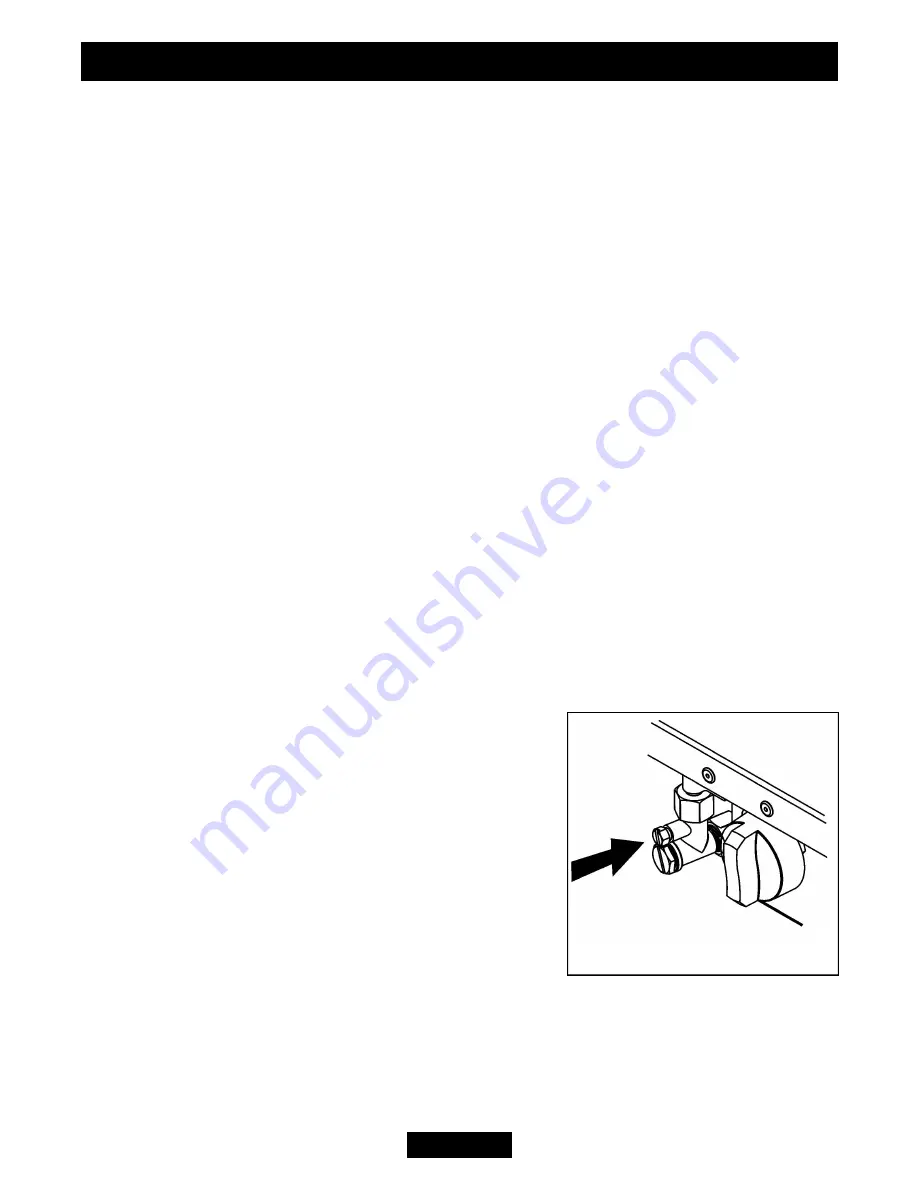
Check the inlet pressure by fitting a pressure gauge at
the test point. The test point is on the inlet ‘T’ connector
(See figure 23). Check the pressure with the appliance
alight and set at maximum output.
2.
After checking, turn off the appliance. Remove the
pressure gauge and replace the test point sealing screw.
3.
Relight the appliance. Turn to the maximum output
position and test around the sealing screw for gas
soundness with a suitable leak detection fluid.
Page 21
INSTALLER GUIDE
Figure 23. Pressure test point


