3.10.1.1
‘Hole-in-the-wall’ installations
It is recommended that a hearth should be installed as in figure 3.
If fitting a fascia that has a firefront designed to sit on a hearth, a reduced depth
hearth is recommended. It is recommended that the reduced hearth has a depth
from the fixing plane of the fire of 100mm minimum. This is necessary to support
the lower front casting. The heat engine must be installed so that distance from
the base of the fireplace opening in the wall to the finished floor level shall be at
least 100mm. Where there is no floor covering or carpet, and the floor is of a
type that is likely to be covered in such a way in the future, then the distance
from the base of the fireplace opening in the wall to the floor level should be
increased to at least 175mm.
If fitting a fascia that does not have a separate firefront and a hearth is not fitted,
the heat engine must be installed so that distance from the base of the fireplace
opening in the wall to the finished floor level shall be at least 100mm. Where
there is no floor covering or carpet and the floor is of a type that is likely to be
covered in such a way in the future then the distance from the base of the
fireplace opening in the wall to the floor level should be increased to at least
175mm.
To protect from the risk of burns and ignition of clothing a tactile separator shall
be used. The hearth detailed in section 3.8 meets the requirements for a tactile
separator. If this is not used then a 672mm long fender, kerb, horizontal bar, or
other barrier, being fixed
not less than 50mm
above floor level and
positioned 300mm in front
of the fixing plane of the
fire will meet the
requirement.
3.10.2
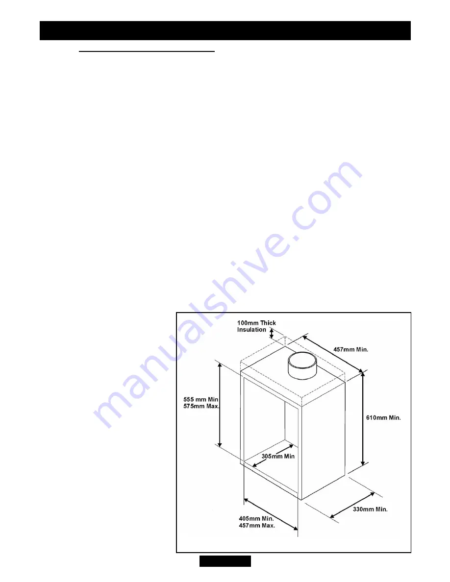
Metal flue box and
hearth.
To a fireplace incorporating a
metal flue box complying with
the constructional requirements
of the current edition of BS715.
The dimensions of the flue box
must conform to those shown
in figure 5.
The top of the metal flue box
must be covered with a
100mm layer of mineral wool
or equivalent insulation.
Page 14
©
Baxi Heating U.K. Limited 2010.
Figure 5. Metal flue box dimensions
INSTALLER GUIDE


