16.1 Checking the aeration setting of the burner.
1.
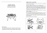
The aeration shutter is factory set and should
not require adjustment. If the shutter is not as
shown in figure 26 and requires adjustment,
loosen the two aeration shutter screws, slide the
aeration shutter to the position shown in figure 26
and tighten the fixing screws.
16.2 To remove the fascia.
1.
The installer and owner guide for the fascia is
supplied with the fascia. This guide should have
been placed inside or attached to this guide.
16.3 To remove the complete burner unit.
1.
Remove the firefront and place in a safe position.
2.
Remove the fascia (See section 16.2)
3.
Remove the ceramic fuel effect.
The installer and owner guide for the ceramic fuel
effect is supplied with the fascia and should have been placed inside or attached to
this guide. It is important that the ceramic fuel effect guide is followed when fitting the
ceramic fuel effect.
4.
Close the valve in the inlet ‘T’
connector .
5.
Disconnect the appliance from the
inlet ‘T’ connector.
6.
Remove the two burner securing
screws (See figure 27).
7.
Lift the burner clear of the convection
box.
8.
Replace in the reverse order.
16.4 To remove the pilot unit.
1.
Remove the complete burner unit (See section
16.3).
2.
Detach the pilot pipe from the pilot unit.
3.
Detach the thermocouple from the gas valve.
4.
Detach the electrode lead from the underside of
the electrode tab.
5.
Remove the two screws securing the pilot unit
(See figure 28).
6.
Refit in the reverse order.
Note:
The pilot unit is an atmosphere sensing
device. It must be replaced as a whole
assembly. Its individual components
are not separately replaceable.
Page 32
©
Baxi Heating U.K. Limited 2010.
Figure 28. Pilot unit removal
Figure 27. Burner attachment points
INSTALLER GUIDE
Figure 26. Aeration shutter setting


