Stove body
The stove is supplied with a locked door. Using a suitable sized spanner, turn the
locking bolt on the front of the door in a counter clockwise direction. Carefully remove
and unpack the contents of the stove.
The stove body contains the following:
1 Burner module.
1 Inlet ‘T’ connector with nut and olive.
1 Vent switch and mounting bracket assembly.
1 Diverter box.
1 Down draught diverter.
1 Control knob assembly.
4. STOVE SET UP
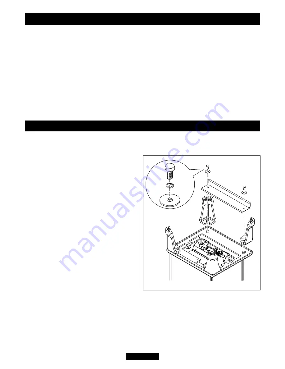
Legs and lower casting cover.
(See figure 1).
1.
Locate the four legs to the underside of
the casting body. There are two feet with
holes in the base. We recommend that
these be placed at the rear of the stove.
2.
Place the front cover casting on top of
the front legs.
3.
Secure the legs and front cover casting
to the underside of the casting body using
the bolts and washers supplied.The bolts
should have the locking washer added first
followed by the flat washer.
4.
This appliance is supplied with a flue
restrictor for use where the flue draught is
excessive. Fit the restrictor as in point 1
below. There may however, be certain
circumstances where fitting the restrictor
causes the fire to fail the spillage test. In
such cases the restrictor will have to be
removed. After removal conduct the
spillage check again.
Page 6
INSTALLER GUIDE
©
Baxi Heating U.K. Limited 2007.
Figure 1.


