6.
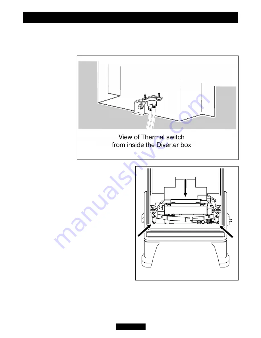
The Thermal Switch should be fitted to the inside of the Diverter Box as in figure 4.
Secure using the nut and bolt supplied. Never modify the fixing bracket and always
ensure that the switch is fitted correctly. NEVER USE THE STOVE IF THE THERMAL
SAFETY SWITCH HAS BEEN REMOVED OR IF IT IS DAMAGED IN ANY WAY.
7.
Locate the diveter box to the rear of the
stove body and secure in place using the
bolts and washers supplied.
8.
Offer the burner module into the stove
and connect the thermal switch leads to the
tags mid way along the thermocouple.
9.
Locate the burner assembly inside the
stove body as in figure 5 (The outer front of
the stove is not shown for clarity). The rear
leg of the burner should sit on the rear of
the casting. Secure using the three screws
supplied The screw locations are shown ion
figure 5).
10.
Secure the control knob assembly to the
gas valve, the screw tail should secure onto
the flat on the gas valve spindle.
Page 8
INSTALLER GUIDE
©
Baxi Heating U.K. Limited 2007.
Figure 5.
Figure 4.


