background image

33

0206_2605

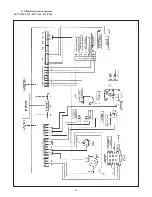
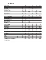
27.1 Illustrated wiring diagram

LUNA HT 280 - HT 330

Summary of Contents for Luna HT

Page 1: ...boilers floor standing boilers electrical water heaters and steel heating plates has obtained the CSQ certificate of conformity to the UNI EN ISO 9001 norms This certificate guarantees that the Quality System applied at the BAXI S p A factory in Bassano del Grappa where your boiler was produced meets the standards of the UNI EN ISO 9001 norm which is the strictest and concerns all organization sta...

Page 2: ...seful information which will help you to run your boiler correctly and efficiently Do not leave any parts of the packaging plastic bags polystyrene etc within children s reach as they are a potential source of danger BAXI boilers bear the CE mark in compliance with the basic requirements as laid down in the following Directives Gas Directive 90 396 CEE Performance Directive 92 42 CEE Electromagnet...

Page 3: ...r size 13 Fittings present in the packaging 14 Installation of flue and air ducts 14 Connecting the mains supply 18 Gas change modalities 24 Setting the boiler parameters 26 Control and operation devices 27 Positioning of the ignition and flame sensing electrode 28 Check of combustion parameters 28 Activating the flue sweeper function 28 Output pump head performances 29 How to disassemble the DHW ...

Page 4: ...d to heat water at a lower than boiling temperature at atmospheric pressure The boiler must be connected to a central heating system and to a domestic hot water supply system in compliance with its performances and output power Have the boiler installed by a Qualified Service Engineer and ensure the following operations are accomplished a accurate purging of the whole pipework in order to remove a...

Page 5: ...ISPLAY SYMBOLS Central heating mode setting key Data display reset key Parameter setting key increase value Parameter setting key decrease value Program access and scroll key Program access and scroll keys Reset key Domestic hot water temperature setting key Central heating water temperature setting key Domestic hot water on off key Resettable alarm warning Flame present on Outdoor temperature Sta...

Page 6: ...e pressed to activate or deactivate this function which is identified on the display by a black cursor line under the symbol 4 Reset key In case of a fault referred to in point 3 7 Faults and resetting the boiler the boiler can be restarted by pressing this key for at least two seconds If this key is pressed with no fault present the display will show the message E153 and the same key has to be pr...

Page 7: ... domestic hot water modes 3 5 1 Setting the daily times for central heating mode operation Press either of the keys to access the programming function a press these keys until the display shows P11 referring to the program start time b press the keys to set the time press the key the display will show P12 referring to the program end time repeat the operations described in points a and b until the...

Page 8: ...ily period of domestic hot water production Start of second daily period of domestic hot water production End of second daily period of domestic hot water production Start of third daily period of domestic hot water production Fine End of third daily period of domestic hot water production Reset of daily central heating and domestic hot water production programs factory settings Press the keys tog...

Page 9: ...ervice centre call the authorised service centre switch off the electricity supply to the boiler for 10 seconds if the fault persists call the authorised service centre press the key again about 2 seconds Press and hold reset button 2 seconds approx then press again when warning E153 appears call the authorised service centre check that the system is at the rated pressure refer to the section on f...

Page 10: ...e pressure gauge 11 is 1 to 1 5 bar with boiler not operating In case of overpressure open the boiler drain valve In case the pressure is lower open the boiler filling tap Figure 5a or 5b We recommend you open the tap very slowly in order to let off the air In case pressure drops occur frequently have the boiler checked by a Qualified Service Engineer 4 Filling the boiler 020503_0400 Boiler fillin...

Page 11: ... the system heating flow temperature drops below 5 C The frost protection function is enabled if electrical supply to the boiler is on the gas service cock is open the system pressure is as required the boiler is not blocked These boilers produced for natural gas can be converted to work with LPG Any gas change must be effected by a Qualified Service Engineer 7 Gas change To maintain efficient and...

Page 12: ...ions 2 Heating circuit 2 1 new system Before proceeding with installation of the boiler the system must be cleaned and flushed out thoroughly to eliminate residual thread cutting swarf solder and solvents if any using suitable proprietary products 2 2 existing system Before proceeding with installation of the boiler the system must be cleaned and flushed out to remove sludge and contaminants using...

Page 13: ...and under the boiler to collect the deposits and scaling which may remain and be circulated in the system after the purge When the boiler is fixed on the template connect the flue and air ducts fittings supplied by the manufacturer according to the instructions given in the following sections Connect the condensate outlet to the siphon supplied with the boiler Connect the siphon to a drain making ...

Page 14: ...ns are given together with each accessory C53 The terminals for combustion air intake and for the expulsion of combustion products must not be provided for on opposite walls of the building C63 The maximum pressure drop of the ducts must not exceed 100 Pa The ducts must be certified for the specific use and for a temperature of over 100 C The chimney flue must be certified in accordance with the p...

Page 15: ...flue air duct in any direction as it can rotate by 360 It can moreover be used as a supplementary bend and be coupled with a coaxial duct or a 45 bend If the flue outlet is placed outside the flue air ducting must protrude at least 18mm out of the wall to allow alluminium weathering tile to be fitted and sealed to avoid water leakages Ensure a minimum downward slope of 1 cm towards the outside per...

Page 16: ... gases both outside the building and into single flue ducts Comburant air may be drawn in at a different site from where the flue terminal is located The splitting kit consists of a flue duct adaptor 100 80 and of an air duct adaptor For the air duct adaptor fit the screws and seals previously removed from the cap 011015_0100 flue duct adaptor Intake air duct adaptor The 90 bend allows to connect ...

Page 17: ...d horizontal flue terminals installation options IMPORTANT Ensure a minimum downward slope of 1 cm toward the outside per each metre of duct length Make sure that the exhaust and intake ducts are securely fixed to the walls L1 L2 max 80 m L max 15 m 010828_0500 010828_06 00 The maximum length of the suction duct must be 15 metres ...

Page 18: ... compliance with the applicable laws and regulations Connect the boiler to a 220 230V monophase ground power supply by means of the three pin cable supplied with it and make sure you connect polarities correctly Use a double pole switch with a contact separation of at least 3mm in both poles In case you replace the power supply cable fit a HAR H05 VV F 3x0 75mm2 cable with an 8mm diameter max The ...

Page 19: ...e instructions in the connecting a zone system section 15 2 Connecting the QAA73 temperature regulator The SIEMENS model QAA73 temperature regulator optional accessory must be connected to terminals 1 2 of terminal board M2 in figure 11 The jumper across terminals 3 4 provided for connection of a room temperature thermostat must be removed The settings of the domestic hot water temperature and dom...

Page 20: ... TSP HC 1h TSP HC TSP DHW Parameter HC1 gradient Selection of central heating circuit temperature curve kt HC1 max output Central heating system maximum output temperature Type of building Room compensation Activation deactivation of the influence of the room temperature If it is deactivated the outdoor temperature sensor must be installed Automatic adaptation of the temperature curve kt in relati...

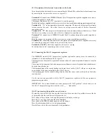
Page 21: ...not reached inside the premises for central heating b with QAA73 temperature regulator The temperature curve kt must be selected by setting parameter 70 HC1 gradient of the QAA73 temperature control device as described in section 15 2 QAA73 parameters which can be set by the installation service engineer See graph 3 for selecting the curve referred to a room temperature of 20 C The curve is shifte...

Page 22: ...e boiler control panel in accordance with the instructions provided for the user in this manual b with QAA73 temperature control device The zone valve or pump relating to the room controlled by the QAA73 temperature control device must be supplied with electricity by means of terminals a b of terminal board M1 in figure 11 The contact relating to the request for operation of the other zones must b...

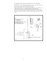
Page 23: ...re 11 first removing the electrical heating element fitted The sensor element of the NTC probe must be fitted into the well provided on the water heater The domestic hot water temperature can be set and the timed domestic hot water program selected directly on the boiler control panel as described in the instructions provided for the user in this manual Figure 13 0207_0904 KEY UB domestic hot wate...

Page 24: ...t regulation screw K on the gas valve Turn the screw clockwise to increase the concentration of CO2 and anticlockwise to reduce it 16 Gas change modalities 020429_0400 Figure 15 020523_0700 Figure 14 Pi Gas supply pressure connection point PO Gas pressure to burner connection point P Pressure connection point for measurement of the OFFSET Pl Air signal input from fan V Gas flow adjuster screw K OF...

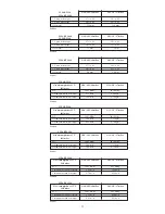
Page 25: ...onsumption at min heat output 0 74 m3 h 0 54 kg h Table 2d LUNA HT 1 120 Gas consumption at 15 C G20 2H 20 mbar G31 3P 37 mbar 1013 mbar PCI 34 02 MJ m3 46 3 MJ kg Consumption at max heat output 1 31 m3 h 0 96 kg h Consumption at min heat output 0 42 m3 h 0 31 kg h Table 2e LUNA HT 330 Gas consumption at 15 C G20 2H 20 mbar G31 3P 37 mbar 1013 mbar PCI 34 02 MJ m3 46 3 MJ kg Consumption at max hea...

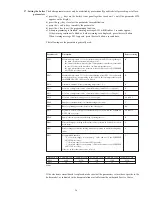
Page 26: ... time in central heating mode min Burner operating pause time between two start ups s Hydraulic system setting see instructions provided with the SIEMENS AGU2 500 accessory Pump three way valve anti blocking operating time s Heat exchanger preheating holding time after operation in domestic hot water mode min Heat exchanger preheating holding time after operation in central heating mode min Progra...

Page 27: ...e hydraulic assembly allows the main burner to light provided the pump head is as required and protects the flue water exchanger from possible lacks of water or blockings of the pump Supplementary running of the pump The electronically controlled supplementary running of the pump lasts 3 minutes when the boiler is in the central heating mode after the burner has switched off due to a room thermost...

Page 28: ...ements of the following combustion products temperature concentration of oxygen O2 or alternatively of carbon dioxyde CO2 concentration of carbon monoxyde CO The comburant air temperature must be measured at the test point connected to the air inlet duct 20 Check of combustion parameters Figure 17 020429_0300 flue gas combustion air gasket To facilitate measurement of the combustion efficiency and...

Page 29: ...he stainless steel plate type DHW heat exchanger is easily disassembled with a screwdriver by operating as described below drain if possible only the boiler system through the drain tap drain the DHW system from water remove the circulation pump remove the two srews right in front of you securing the DHW heat exchanger and pull it off its seat Figure 19 23 How to disassemble the DHW heat exchanger...

Page 30: ...its filter remove the impurities Important in the event of replacements and or cleaning of the O rings on the hydraulic unit do not use oil or grease as lubricant but exclusively Molykote 111 To ensure the boiler operates at peak efficiency the following checks must be performed every year check on the appearance and tightness of the gas and combustion circuit gaskets check on the condition and po...

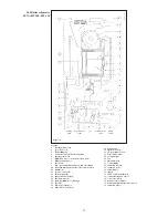
Page 31: ...14 pump and air separator 15 automatic air vent 16 plate type DHW heat exchanger 17 gas valve 18 flue water exchanger 19 flame detector electrode 20 main burner 21 ignition electrode 22 air gas mixture header 23 mixer with venturi 24 gas diaphragm 25 fan 26 flue thermostat 27 coaxial fitting 28 automatic air vent 29 expansion vessel 30 fumes header 31 siphon 32 105 C overheat thermostat 33 central...

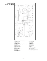
Page 32: ...ef valve 13 boiler drain point 14 pump and air separator 15 automatic air vent 17 gas valve 18 flue water exchanger 19 flame detector electrode 20 main burner 21 ignition electrode 22 air gas mixture header 23 mixer with venturi 24 gas diaphragm 25 fan 26 flue thermostat 27 coaxial fitting 28 automatic air vent 29 expansion vessel 30 fumes header 31 siphon 32 105 C overheat thermostat 33 central h...

Page 33: ...33 0206_2605 27 1 Illustrated wiring diagram LUNA HT 280 HT 330 ...

Page 34: ...34 27 2 Illustrated wiring diagram LUNA HT 1 120 HT 1 240 HT 1 280 0206_2604 ...

Page 35: ...system min output l min 2 5 2 5 DHW production at T 25 C l min 16 1 18 9 DHW production at T 35 C l min 11 5 13 5 Specific output D l min 12 9 15 3 Concentric flue duct diameter mm 60 60 60 60 60 Concentric air duct diameter mm 100 100 100 100 100 2 pipe flue duct diameter mm 80 80 80 80 80 2 pipe air duct diameter mm 80 80 80 80 80 Max flue mass flow rate kg s 0 014 0 016 0 006 0 012 0 014 Min fl...

Page 36: ... in its commitment to constantly improve its products reserves the right to alter the specifications contained herein at any time and without previous warning These Instructions are only meant to provide consumers with use information and under no circumstance should they be construed as a contract with a third party ...

Reviews: