background image

23

Electrical Supply

The electrical supply for this Solo 2 RS depends on
the design of the central heating system i.e.

Gravity DHW and Pumped Central Heating - 3 core
cable.

Fully Pumped, Open Vented with rising primaries - 4
core cable. However, 3 core cable can be used if the

timed pump overrun and overheat thermostat are

disconnected.

Sealed Systems and Fully Pumped

Systems with dropping pipework - 4

core cable must be used.

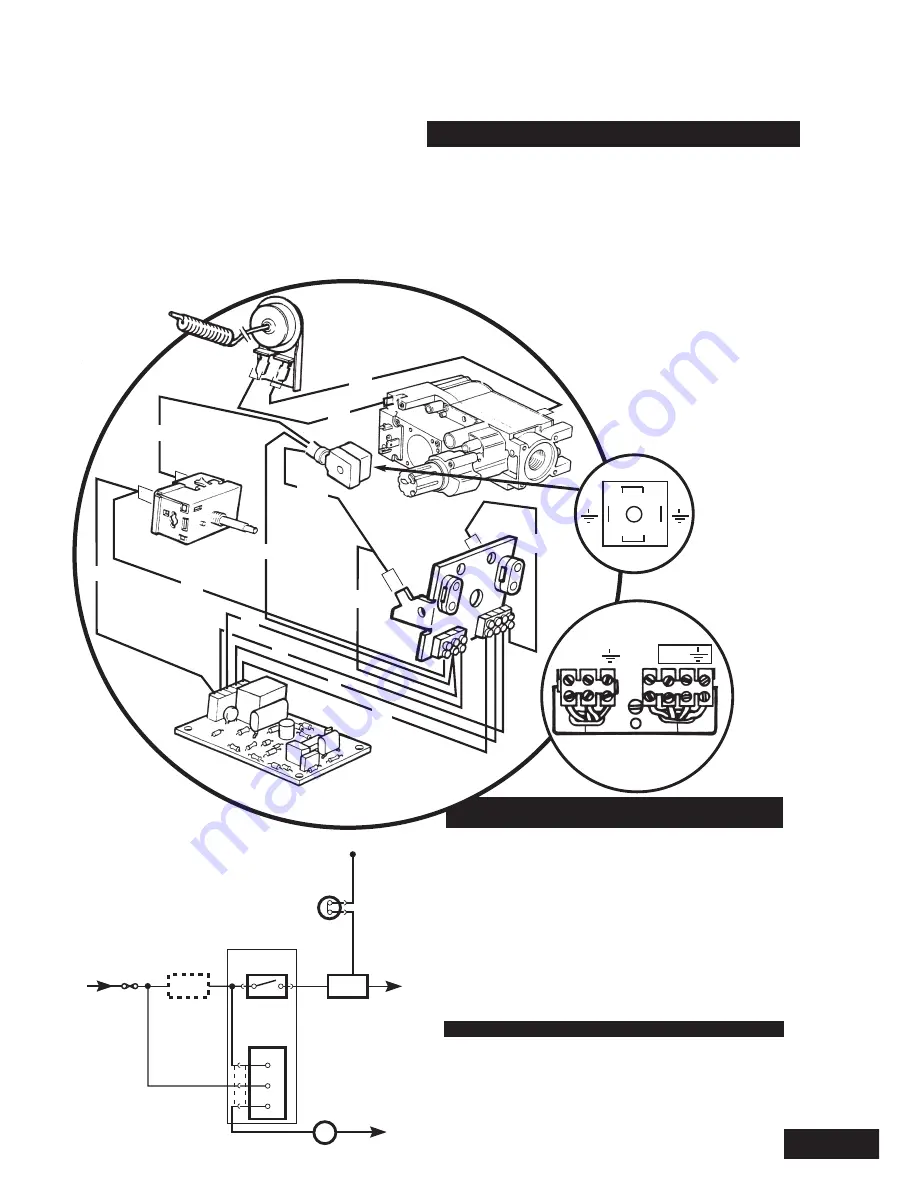
Detail of the electrical supply

for the various system

designs can be found below.

FOR FULLY PUMPED AND SEALED

SYSTEMS

The recommended cable for connection to the
appliance terminal strip is 4-core 0.75mm

2

(24 x 0.2mm dia) P.V.C. IEC 53 code 227 (heat
resistant).

External wiring must be correctly earthed and
polarised and in accordance with current I.E.E. wiring
regulations.

The mains supply required is 230V ~ 50Hz fused at
3A.

WARNING

THIS APPLIANCE MUST BE EARTHED.

NOTE: The method of connection to the electricity
supply must facilitate complete electrical isolation of
the appliance.

Thermocouple

Overheat

Thermostat

Fuse

3A

L

N

N

External

Programmer

or

br

w

w

2

3

Pump

Gas 

Valve

Pump-Overrun

Timer

r

br

Boiler

Thermostat

220/240V

KEY

br -

brown

b -

blue

g/y - green/yellow
or -

orange

r

-

red

w -

white

g/y

w

w

br

g/y

g/y

b

or

or

b

b

br

r

Overheat 

thermostat 

Gas valve

Boiler

thermostat 

Pump Overrun
Circuit

S/L N

P/L

Pump

L  N

2

1

view in arrow

direction

Summary of Contents for Solo 2 30 RS

Page 1: ...Please leave these Instructions with the User Baxi Solo 2 RS Range Wall Mounted Room Sealed Gas Fired Central Heating Boilers Installation and Servicing Instructions ...

Page 2: ...2 Natural Gas Baxi Solo 2 60 RS G C No 41 077 79 Baxi Solo 2 50 RS G C No 41 077 78 Baxi Solo 2 40 RS G C No 41 077 77 Baxi Solo 2 30 RS G C No 41 077 76 ...

Page 3: ...keep ahead of changing trends we have made a commitment to develop new ideas using the latest technology with the aim of continuing to make the products that customers want to buy Baxi is also the largest manufacturing partnership in the country Everyone who works at the company has a commitment to quality because as shareholders we know that satisfied customers mean continued success We hope you ...

Page 4: ...as Supply Electrical Supply PAGE 15 25 Initial Preparation Flue Preparation Fitting the Wall Mounting Plate Fitting the Flue Duct Terminal Guard Fitting a Terminal Guard Fitting the Boiler Water Connections Pipe Routes Fully Pumped System Sealed System Gravity Hot Water System Gas Connection Electrical Supply PAGE 26 27 PAGE 28 PAGE 29 PAGE 30 32 Dismantling the Boiler Cleaning the Burner Injector...

Page 5: ...ebris accumulated in and around the appliance This should be performed before and after working on the installation It is recommended that any replaced item s are not broken up but sealed within heavy duty polythene bags and clearly labelled R C F waste This is not classified as hazardous waste and may be disposed of at a tipping site licensed for the disposal of industrial waste Protective clothi...

Page 6: ... 38 750 Heat Output Max Min kW 11 72 9 09 Btu h 40 000 31 000 Burner Pressure Max Min mbar 16 3 0 5 10 3 0 5 in wg 6 5 0 2 4 1 0 2 Gas Connection RC1 2 1 2in BSPT Electrical Supply 230V 50Hz fused 3A Controls on off boiler thermostat with pilot thermocouple cut out overheat thermostat on fully pumped applications only Heat Exchanger cast iron monobloc Lifting Weight 37 3 kg 82 1 lbs Water Content ...

Page 7: ...0 Heat Output Max Min kW 17 58 14 95 Btu h 60 000 51 000 Burner Pressure Max Min mbar 16 0 0 5 12 0 0 5 in wg 6 4 0 2 4 8 0 2 Gas Connection RC1 2 1 2in BSPT Electrical Supply 230V 50Hz fused 3A Controls on off boiler thermostat with pilot thermocouple cut out overheat thermostat on fully pumped applications only Heat Exchanger cast iron monobloc Lifting Weight 37 3 kg 82 1 lbs Water Content 2 1 l...

Page 8: ... a pump overrun device which allows the removal of residual heat from the boiler NOTE The pump overrun will operate for approximately 3 minutes The system design must therefore always provide an open circuit for water to circulate between the boiler flow and return If a system has an open circuit a bypass is not required A system using a 3 port diverter valve does not normally require a bypass and...

Page 9: ...mmended that the system is designed for an 11 C 20 F drop in temperature across the system In systems using non metallic pipework it is necessary to use copper pipe for the boiler Flow and Return The copper must extend at least 1 metre from the boiler and include any branches The copper pipe must not be insulated Fully Pumped Open Vented Systems Low Head Installation Using a close couple arrangeme...

Page 10: ...by means of a connection close to the inlet side of the circulating pump in accordance with the manufacturers instructions the connecting pipe being unrestricted and not less than 15mm 1 2 in nominal size The volume of the vessel should be suitable for the system water content and the nitrogen or air charge pressure should not be less than the system static head Further details of sealed system de...

Page 11: ...tem must be designed to prevent reverse circulation Pipes should be laid to maximum fall avoiding points of possible air lock If the domestic hot water temperature is controlled by a cylinder thermostat and zone valve it is recommended that a bypass is installed in the gravity circuit One method is to install a bathroom radiator fitted with two lock shield valves Mechanical valves which allow the ...

Page 12: ...ude the necessary clearances around the appliance for case removal spanner access and air movement Additional clearances may be required for the passage of pipes around local obstructions such as joists running parallel to the front face of the appliance If fitted inside a cupboard the clearance of 300mm shown is only necessary when the cupboard door is open A clearance of 5mm 3 16 in is required ...

Page 13: ...ll 300 L For an opening in a car port e g door window into a dwelling 1200 WARNING If a terminal is less than 2 metres 783 4 in above a balcony above ground or above a flat roof to which people have access then a suitable terminal guard must be provided Flue Dimensions Recommendations for flues are given in BS 5440 1 The standard flue terminal supplied with the appliance is suitable for use with w...

Page 14: ... the appliance is of adequate size Do not use pipes of a smaller diameter than the appliance gas connection Electrical Supply External wiring must be correcty earthed polarized and in accordance with CURRENT I E E WIRING REGULATIONS The mains supply is 230V 50Hz fused at 3A NOTE The method of connection to the electricity supply must facilitate complete electrical isolation of the appliance prefer...

Page 15: ...ting the lower edge of the boiler is level with the lower edge of the units and is correctly spaced If fitting the appliance in a compartment or cupboard with suitable air vents see Ventilation of Compartments ensure that the bottom edge of the template is level with the lower edge of the units and is correctly spaced Two holes are provided on the template to allow gas and electrical supplies to b...

Page 16: ...ss between 102mm 4in and 280mm 11in air duct and flue duct are required to be shortened Using the indication on the duct mark accordingly to table below Bend tabs as shown Using tin snips cut around ducts at appropriate mark Remove any sharp edges Wall Thickness Air Duct Flue Duct Flue Trim Cut off Wall Thickness 3in 203mm 280mm 8in 11in 6in 127mm 203mm 5in 8in 7in 102mm 127mm 4in 5in 16 ...

Page 17: ...e two tabs should be positioned at the bottom Slide air duct over inner duct until tabs contact wall surface Ensure air duct is horizontal and square to wall face Using sealing tape supplied make good the joint on inside of the two ducts Make good with cement mortar between the outside wall and duct Sealing Tape Air Duct Tab Inner Duct 17 ...

Page 18: ...flue duct inside air duct to engage flue duct on boiler noting correct positioning as labelled Secure flue duct flue trim to air duct with four screws provided in the kit Remove label from duct Flue Trim Sealing Tape Air Duct Tabs Air Duct Flue Duct 18 Label ...

Page 19: ...isted below can be contacted for terminal sizes and guard model numbers Quinnell Barrett Quinnell 884 Old Kent Road London SE15 1NL Tel 071 639 1357 Tower Flue Components Ltd Tower House Vale Rise Tonbridge Kent Tel 0732 351555 Fitting a Terminal Guard Position the guard over the terminal on the outside wall Ensure guard is equally spaced about terminal Mark fixing positions Drill and plug fixing ...

Page 20: ... passed and will allow the appliance to perform satisfactorily on gravity circulation NOTE Even though the overheat thermostat is not operational it must not be removed from the pocket in the heat exchanger except during servicing Lift boiler and engage centrally the back bottom edge into the hook bracket on the mounting plate Rotate the boiler back to the mounting plate to engage two studs and sp...

Page 21: ...ted to the back plate Pipes may also be routed to drop down within outer case Spaces are available at both sides If pipes are routed to drop down within the outercase vents are required It is recommended that fittings A are of copper capillary type It is recommended that fittings B are compression type Fully Pumped System For fully pumped system connect to tails marked F and R Sealed System For se...

Page 22: ...own Ensure that pipes run perpendicular to the wall to allow fitting of the outercase Gas Connection Gas connection is made on the union gas service tap female 1 2 in B S P thread Dimension shown will ensure that gas pipe does not interfere with outer case or any downward routed pipes Injector Washer Gravity Flow 28mm Pumped Flow 22mm Gravity Return 28mm Pumped Return 22mm Tee with Injector Washer...

Page 23: ...the appliance terminal strip is 4 core 0 75mm2 24 x 0 2mm dia P V C IEC 53 code 227 heat resistant External wiring must be correctly earthed and polarised and in accordance with current I E E wiring regulations The mains supply required is 230V 50Hz fused at 3A WARNING THIS APPLIANCE MUST BE EARTHED NOTE The method of connection to the electricity supply must facilitate complete electrical isolati...

Page 24: ...he right hand cable clamp Fit the pump outlet as follows Connect the pump earth to the terminal marked Connect the pump neutral to the terminal marked N Connect the pump live to the terminal marked L Secure the cable in place with the left hand cable clamp Replace the electrical cover and securing screw A cable clip is supplied in the kit to secure the cable to the bottom of the combustion box In ...

Page 25: ...ode 227 heat resistant WARNING This appliance must be earthed Loosen securing screw sufficiently for the electrical cover to be removed from the thermostat box Bare back input cable to dimensions shown Fit input cable to terminal block on left passing through the grip provided The pump should be wired to the junction box or programmer Replace electrical cover and securing screw A cable clip is sup...

Page 26: ...osition marked O Slacken burner pressure test point screw Connect pressure gauge Press gas control knob fully inwards and hold Press in igniter button and release Repeat until pilot ignites Continue to hold in gas control knob for approximately 15 seconds and then release Pilot should stay alight Check the appearance of the pilot flame to ensure that it envelops the tip of the thermocouple and is ...

Page 27: ...s the pump running fully pumped systems only when any external control switches the appliance off To check the operation of this turn programmer time switch off the pump should continue to run for approximately 3 minutes and then stop The boiler and system should be run and then flushed and treated in accordance with BS7593 1992 and the flushing agent inhibitor manufacturers instructions When all ...

Page 28: ...ter case up to the hooks on the top of the combustion box ensuring that it engages Secure the outer case using the two screws and washers that are supplied Replace the lower front door panel Instruct the user in the operation of the boiler Hand over the User s and Installation Instructions and the Log Book to the user giving advice on the necessity of regular servicing FITTING THE OUTER CASE 1 2 3...

Page 29: ... the control should it ever cut out Remove the lower door panel by following the sequence of diagrams Reach into the outer case and locate the reset button adjacent to the control box Press the button to reset the overheat thermostat The boiler must be reignited manually NOTE Any interruption to the electricity supply may cause the device to operate 1 2 3 ...

Page 30: ...ence of diagrams To remove the outer case from the boiler take out the two screws and washers Draw outer case forward and clear of the boiler 1 Turn off gas supply at the service tap and disconnect the union 2 Disconnect the electrical plug on the gas valve by removing screw and pulling forward 3 Disconnect the two wires from the overheat thermostat 4 Loosen the screw on the capillary retaining wa...

Page 31: ...Remove the two screws fixing the burner brackets to the combustion chamber door Remove burner assembly noting position of pilot shield O ring and gasket Remove the two screws fixing the mounting bracket Remove the four screws to separate the manifold from the blade assembly Clean venturies Unscrew injectors clean carefully and replace Check seal around the door and replace if necessary Reassemble ...

Page 32: ...ed The heat exchanger can now be easily cleaned thoroughly Remove any obstructions from flue outlet and air inlet Remove dirt and debris from bottom of combustion box Reassemble all components in reverse order Check burner setting pressure and gas rate Recommission the boiler before use checking for gas soundness and ensuring all controls are working correctly Complete the relevant section of the ...

Page 33: ...that electrical and gas supplies are isolated before the work is started Remove the outer case lower door panel by following the sequence of diagrams Remove the outer case from the boiler by unscrewing the two screws and washers lift the case to clear the two hooks at the top of the combustion box Draw the outer case clear of the boiler 1 2 3 ...

Page 34: ...the gas valve Reassemble in reverse order CAUTION Do not overtighten Piezo Igniter Withdraw and disconnect electrode lead Remove retaining nut holding piezo igniter to bracket Exchange igniter for new and reassemble Solenoid Operator Ensure electrical supply is isolated Disconnect the electrical plug by removing the screw and pulling forward Remove solenoid operator by unscrewing fixing screws Exc...

Page 35: ...ngaged Pilot Injector Disconnect nuts on pilot supply tube and remove Extract injector using a small screwdriver Fit new injector and reassemble Pilot Bracket Gasket Disconnect thermocouple spark electrode and pilot feed pipe from pilot bracket DO NOT remove pilot viewing window Carefully remove pilot injector Undo the four screws retaining the bracket to the door and remove Check pilot gasket and...

Page 36: ...e thermostat pocket Remove the locknut and withdraw the overheat thermostat from the bracket Disconnect the two wires from the overheat thermostat and refit them to the new component Reassemble in reverse order Care must be taken to align the overheat thermostat capillary with the groove in the main thermostat phial NOTE The overheat thermostat capillary may be somewhat longer than necessary Exces...

Page 37: ...mps Boilers converted for use on gravity D H W will have wiring only to the left hand terminal strip 5 Unfasten the screws holding the thermostat box to its bracket on the boiler combustion box The thermostat box is now free of the boiler 6 Remove the rear part of the thermostat box by removing the screws at the side 7 Release the locknut securing the main boiler thermostat to the mounting plate 8...

Page 38: ...Disconnect the electrical plug on the gas valve by removing screw and pulling forward 3 Disconnect the two wires from the overheat thermostat 4 Loosen the screw on the capillary retaining washer allowing the washer to move freely Release the capillaries from the clips on the side of the combustion box Remove both phials from the thermostat pocket 5 Remove brass sealing plug with fibre washer 6 Loo...

Page 39: ...hen proceed as follows Remove the two screws fixing the mounting brackets Remove the four screws to separate the manifold from the blade assembly Unscrew injectors and fit new ones Reassemble the burner and attach to controls door in reverse order Gas Valve The gas valve fitted to the appliance is of the stepped ignition type Release fixing nuts on pilot feed pipe and thermocouple at gas valve whi...

Page 40: ...ble in reverse order To replace side insulation panels remove fixing screws Slide panel down and away from location Fit new side insulation panel and reassemble in reverse order To replace rear insulation panel remove the side insulation panels by removing fixing screws Slide rear insulation panel down and away from location Fit new rear insulation panel and reassemble in reverse order ...

Page 41: ...y central heating pump not functioning correctly pump overrun timer faulty no by pass by pass closed installation fault no permanent live pump not wired to boiler incorrect use i e turning off at isolation switch Thermocouple damaged connections between thermocouple overheat thermostat and gas valve faulty or poor overheat thermostat faulty SYMPTOM Overheat cut off device operates repeatedly Overh...

Page 42: ...5 45 Burner Boiler 30 170 530 232515 46 Burner Boiler 40 170 531 232514 47 Burner Boiler 50 170 532 232513 48 Burner Boiler 60 170 533 232512 60 Burner Pilot Assy All models 379 300 233122 59 Injector Pilot All models 379 301 232150 63 Thermocouple All models 379 302 232159 64 Electrode Pilot Ign All models 379 303 232151 29 Thermostat Boiler All models 379 306 232156 38 Knob Thermostat All models...

Page 43: ...ducts for the domestic heating market Gas Central Heating Boilers Wall Floor and Fireside models Independent Gas Fires Renewal Firefronts Gas Wall Heaters Solid Fuel Fires If you require information on any of these products please write to the Sales Department ...

Page 44: ...Road Bamber Bridge Preston Lancashire PR5 6SN www baxi com The Baxi Helplines For General Enquiries 44 0 8706 060 780 For After Sales Service 44 0 8706 096 096 For Technical Enquiries 44 0 8706 049 049 Comp No 232184 Iss 11 6 00 ...

Reviews: