background image

28

TROUBLESHOOTING GUIDE

Troubleshooting Guide 

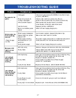
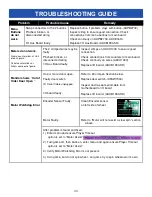
Problem


Probable Cause


Remedy


Dollar Bill  
Acceptor 
not  
functioning


Ensure bill acceptor has 110  
Volts AC. 


Dirt or debris in acceptor slot. 


Ensure acceptor dipswitch is  
set to “always enable” 


Pinched, broken, or  
disconnected wiring. 


Bill acceptor problem. 


Acceptor should cycle stacker at game power up. If not,  
check cable connections to power strip. 

Caution –


110 Volts AC


Clean with bill reader cleaning card. (A5CC9000) 


There are dips on side of acceptor.  
Set to “always enable”  (not harness enable) 


Check wiring from bill acceptor to main board.  
Repair or replace wiring harness. (AAJP9092, AACE1611) 


Refer to troubleshooting section of dollar bill acceptor  
manual included with this game or the diagnostics label  
of the back of the unit. 


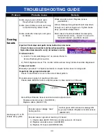
Monitor not  
working.


Power 
down, wait 

minutes 

and power 
up again.


Monitor shows “No 
Signal”  


Monitor VGA cable unplugged. Check the connection at the 2 cables  
to the monitor. (A5CORD11, A5CORD20) 


Check large connection on motherboard from power supply. Ensure  
power supply is running. Refer to Power Supply Diagnostics. 


Faulty motherboard - Replace motherboard. (AAMB9-FHD) 


Monitor has nothing 
at all on power up.


Power cable unplugged  
from monitor. 


Faulty monitor. 


Ensure power is plugged into back of  
monitor, check the connection at the 2  
cables to the monitor, down to power  
strip.(A5CORD1, A5CORD5) 


Replace monitor. (A5CBDI030)


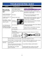
Error on screen at 
power up.


Re-Boot game to see 
if problem still exists.


Check fan on power sup- 
ply, ensure it is turning 


Faulty USB stick 


Faulty motherboard.  


Refer to Power Supply Diagnostics.  Re-

place power Supply 

AACE1625 

if needed. 


Reseat USB software stick into different  

USB socket on motherboard. 
Replace USB software (A5FHD005) 


Replace motherboard. (AAMB9A-FHD) 

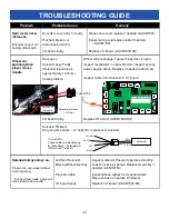
AACE8811


SPEAKER


BILL 

LO COI

AACB1900-SD         


No  
Audio


Volume too low. 


Loose wire. 


Use MP3 or  
Phone to isolate  
problem.


Increase the volume by pressing Menu button, scroll to  
volume slider bar and adjust. 


Check audio cable connections from motherboard to I/O board to speakers 
(A5CEAU010, AACB1900-SD, AACE1605, AACE8811) 


Unplug phono jack from motherboard and plug into the MP3 or phone. 
Then the sound from your device will play through the game speakers. 
If no sound through your device, then replace Motherboard. (AAMB9-FHD)


Summary of Contents for Scooby-Doo

Page 1: ...1 ...

Page 2: ... baytekgames com SALES P 920 822 3951 F 920 822 8936 E sales baytekgames com All games are proudly manufactured at our factory in Pulaski Wisconsin USA JOIN OUR SERVICE FIRST NETWORK This free service is intended to keep you up to date on the latest game information early notification of parts specials pertinent technical bulletins updates on retro fit parts software upgrades and much more Log on ...

Page 3: ...GAME HISTORY 16 TIME AND DATE MENU 17 DIAGNOSTIC INFORMATION 17 GAME STATISTICS 18 TICKET PATTERNS 19 20 MAINBOARD PINOUT 21 WIRING DIAGRAMS 22 25 TROUBLESHOOTING GUIDE 26 33 DOOR OPEN ERROR 34 LIMIT SWITCH MAP 35 HOW TO UPDATE SOFTWARE 36 ADJUSTING ENCODER WHEEL SENSOR 36 37 CARD SWIPE SYSTEM INSTALLATION 38 BRAKE ADJUSTMENT 38 19 PUPPY VIDEO WIZARD ERROR 41 REMOVING THE HANDLE 42 CLEANING THE WI...

Page 4: ...r business is important to us and we hope you enjoy this game as much as we do Your Friends at Bay Tek Games GAME INSPECTION Inspect the game for any damaged loose or missing parts If damage is found please contact your freight carrier first Then contact Bay Tek Games Service Department at 920 822 3951 or e mail them at service baytekgames com for further assistance SCOOBY DOO and all related char...

Page 5: ...5 HOW TO PLAY Lift handle up Pull the handle down using just the right amount of force to win big Win the ticket value displayed on the space that stops under the arrow ...

Page 6: ...NING Use of flammable subtances can cause sever burns or serious injury Always use NON FLAMMABLE solvents for cleaning DO NOT use gasoline kerosene or thinners CAUTION Lifting heavy objects can cause back neck or other injuries Be sure adequate lifting and moving devices are available when unloading unpacking and moving this game ATTENTION Be sure the electrical power matches the game requirements...

Page 7: ... UP GUIDE Remove zip ties from cables on top of the cabinet Route the black power cable over the right side of the cabinet Route the VGA cable along with the 1709 1714 cable bundle over the left side of the cabinet ...

Page 8: ... from the black plastic cover on the back of the marquee and set them aside On the left side of the cabinet lift the marquee up and route the VGA cable and the 1709 1714 cable bundle through the cut out on the bottom of the sleigh marquee Tuck the cable into the channel so the wires don t pinch Pull all excess cable up and through the cut out ...

Page 9: ...ble through the cut out on the bottom of the marquee Tuck the cable into the channel so the wires don t pinch Pull all excess cable up and through the cut out Open the cashbox and get the hardware kit out to secure the marquee to the game This kit will consist of 4 bolts 4 lock washers and 4 flat washers ...

Page 10: ...f the game Hand thread in the bolts lock washers and washers in all four holes before securing to prevent cross threading from happening Once all four bolts are started use a 7 16 socket and fully tighten Plug in the power cords Plug in the 1714 cable housing into the 4003 cable housing ...

Page 11: ... Plug in and tighten the screws on the VGA cable to the monitor on the bottom right hand side Reinstall the black guard over the back of the marquee to protect the wiring Secure the guard using the 8 black screws re moved earlier ...

Page 12: ... Attach the side guards with the bolts flat washers split washers and lock nuts 4 bolts in each side from the inside of the cabinet The 6 bolts circled in RED will only be secured with a split washer and a lock nut The 2 bolts in YELLOW will use a flat washer split washer and a lock nut Plug power cable into standard outlet You are now ready to play ...

Page 13: ...3 MAIN MENU FUNCTIONS Press and hold the MENU button located inside the front door to access the main menu Scroll through the options with the MENU button Make your selections with the MENU SELECT button ...

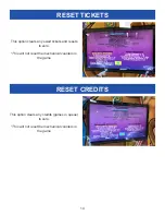
Page 14: ...EDITS This option clears any owed tickets and resets to zero This will not reset the mechanical counters in the game This option clears any credits games in queue to zero This will not reset the mechanical counters in the game ...

Page 15: ...rough volume options on the slider The red arrow shows the current setting This setting is only for the audio played during game play Factory default is highlighted below ATTRACT VOLUME Use the SELECT button to scroll through volume options on the slider The red arrow shows the current setting This setting is only for the audio played during attract mode ...

Page 16: ...TIMEOUT OPTION GAME HISTORY MOTOR ASSIST The game will spin the wheel if the player does not in the time allotted ABANDON GAME The game ends if the player doesn t spin the wheel in the time allotted Factory default is highlighted below Enter the history menu to view past played games and scores THESE OPTIONS ARE DISABLED IN WA STATE GAMES ...

Page 17: ...he first value displays the encoder position 0 36 The second value shows the ticket value the encoder is reading It should match where the wheel is physically The third value shows the notch position on the encoder wheel 1 inside the notch 0 outside the notch INPUTS OUTPUTS Shows the quantity of various button inputs and mechanical outputs BRAKE STATUS Allows you to check your brake during the mai...

Page 18: ...e total number of tickets dispensed since the statistics were last cleared TICKETS PER GAME This will display the average number of tickets won per game TOTAL MOTOR ASSISTS Displays how many times the game had to spin the wheel for the player TOTAL JACKPOTS Shows the total number of jackpot wins since the statistics were last cleared ...

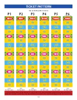
Page 19: ...AME 20 141 AVG TICKETS GAME 23 426 AVG TICKETS GAME 28 841 AVG TICKETS GAME 33 80 AVG TICKETS GAME 35 035 AVG TICKETS GAME P1 500 50 50 50 10 25 10 10 25 10 10 10 10 10 25 10 P2 500 50 50 50 15 40 15 10 25 15 15 40 15 10 25 10 P3 1000 50 50 50 15 25 15 10 40 10 15 25 15 10 40 10 P4 1000 100 100 100 15 75 15 10 25 15 10 75 15 10 25 10 P5 1000 100 100 100 15 40 10 50 25 50 15 40 10 50 25 50 P6 1000 ...

Page 20: ...uide only 59 330 AVG TICKETS GAME 73 394 AVG TICKETS GAME 3 712 AVG TICKETS GAME 3 9997 AVG TICKETS GAME 7 709 AVG TICKETS GAME 13 328 AVG TICKETS GAME P7 1000 250 250 250 15 40 10 10 75 150 15 40 10 150 75 150 P8 1000 500 500 500 10 40 150 50 40 150 10 40 150 50 40 150 P9 100 10 20 10 2 3 5 2 3 5 2 3 5 2 3 5 P10 125 15 25 15 2 3 5 2 3 5 2 3 5 2 3 5 P11 500 25 25 25 2 3 2 5 3 5 2 3 5 5 3 5 P12 500...

Page 21: ...NSOR AACE1608 MOTOR AACE1616 SOLENOID CABLE AACE1606 COUNTERS AACO1000 POWER IN AACE1621 2 BOBBER CHASE LIGHTS AACE1624 NOT USED 2 TICKET DISPENSERS AACE1609 MENU BUTTONS AACE1613 SERIAL PORT TO MOTHERBOARD AACE1614 AACE1900 SERIAL PORT TO MOTHERBOARD AACE1614 SPEAKER LINE OUT A5CEAU010 MONITOR CABLE A5CORD11 AAMB6 ...

Page 22: ...Left Ticket Dispenser AACE1609 Right Ticket Dispenser Not Used AACE1714 Marquee Lighting AACE4001 Comm to Light Control Board AACE1614 Serial Port to Motherboard AACE1613 Menu Buttons Power in from Power Supply AACE1618 Door Open Switches Not Used AACE1605 Speakers A5CEAU010 Speaker Signal In AACE1705 Encoder Sensor AACE1708 Motor AACE1704 Solenoid Not Used AACE4002 5 Volt DC Lights AACB6921 SD Li...

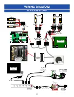
Page 23: ...tional Lights on Side of Wheel AACE1620 White Wheel LED lighting AALS1701 AALS1701 4 3 1 2 AACE1625 Part of power supply To Bill Acceptor Part A5AC9091 AACE1612 AAJP9092 Ground Stud A5OU1000 Outlet Strip AACBDI030 Monitor A5CORD1 AAEX1007 A5CORD5 Power In Cord from wall A5FI9010 Line Filter AACE1716 Power In Cable A5CORD12 AC Power to Power Supply A5CORD5 AAMB9A FHD Motherboard AACE1714 AACE4002 5...

Page 24: ...cables are all Part AACE1619 AACE1702 AACE1701 AACE1703 AACE1700 AACE1703 AACE1600 Front Right Door Switch A5SW7000 Front Le Door Switch A5SW7000 Right Side Switch A5SW7000 Le Side Switch A5SW7000 Back Door Switch A5SW7000 BILL ACCEP TOR LOW TICKET COIN DOOR AACB1900 SD I O Aux Board AACE1705 AACE1605 Speaker AACE8811 Speaker AACE8811 AACB1901 Encoder Sensor Solenoid resistance is 13 Ohms Motor re...

Page 25: ...ally Open To Left Side Ticket Dispenser Part A5TD1 12 Volt Power Enable Signal Com Ground Notch Signal Game Ground AACE3219 P Ticket Tray Cable AASW200 Low Ticket Switch Wired Normally Open AACE1609 AACE1609 Game Counter Ticket Counter AACO1000 To Bill Acceptor Part A5AC9091 AACE1612 Ground Stud AACE1611 AACBL4A DOOR AAJP9092 From Power Strip Menu Button AAPB2700 Menu Select AAPB2700 AACE1613 Blan...

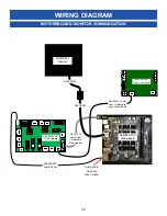
Page 26: ...otherboard BILL ACCEP TOR LOW TICKET COIN DOOR AACB1900 SD I O Aux Board AACBDI030 Monitor AACB6921 SD Light Control Board AACE1614 Comm from I O Board to Motherboard AACE4001 Comm from I O Board to Light Control Board A5CORD11 A5CORD20 A5CEAU010 Audio Cable Audio Cable plugs into Green Socket ...

Page 27: ...d component A bad solenoid or 12 volt short would cause this Refer to Power Supply Diagnostics section Marquee LED lights are not working LED strip faulty Faulty Cable Remove marquee and examine LED strip AACE4003 Check cables from LED strip to I O Aux Board AACE4003 AACE1714 AACB1900 SD Left or Right Wheel White LED s not working LED strip faulty Faulty Cable Faulty I O Aux Board Slide open front...

Page 28: ...er supply is running Refer to Power Supply Diagnostics Faulty motherboard Replace motherboard AAMB9 FHD Monitor has nothing at all on power up Power cable unplugged from monitor Faulty monitor Ensure power is plugged into back of monitor check the connection at the 2 cables to the monitor down to power strip A5CORD1 A5CORD5 Replace monitor A5CBDI030 Error on screen at power up Re Boot game to see ...

Page 29: ...door Open Faulty I O Aux Board Set Game drive voltage threshold to 2 volts Coin signal wires are white and black wires Refer to wiring diagram Check connections from coin switches to I O Aux Board Check continuity on wires AACBL4A DOOR AACE1610 Replace coin mech if faulty Check all 5 door switches Ensure CE1614 cable is connected from I O board to Motherboard Replace I O Aux Board AACB1900 SD Low ...

Page 30: ...t dispenser issue The monitor will show how many tickets should be dispensed If does not match Manually spin wheel 1 complete revolution to ensure home sensor is being read Important Always spin downward Check Ticket Pattern is set to the correct ticket pattern Encoder sensor signal not reaching I O board Check cable AACE1616 from encoder sensor to blue socket on I O board Go to Wheel Encoder Sens...

Page 31: ...ill pay out Flip tickets and load upside down to have large cut notch toward opto sensor Inspect wires as they plug into I O board Swap ticket dispenser cables on I O board to determined that one socket is faulty Wrong ticket amount dispensed Check for the correct amount of tickets showing on monitor Monitor showing correct ticket payout Disconnected loose or broken wires Opto Sensor on ticket dis...

Page 32: ...if game thinks door is open Close all doors Assist motor will try for 2 seconds not see the wheel turning and then deactivate Replace encoder sensor AACB1901 Inspect mechanism on left side door Replace spring if needed A5SREX040 Inspect drive chain that powers wheel Replace if needed A5CH1003 Inspect cable from Assist Motor to I O board Replace I O board AACB1900 SD Motor Problem As motor starts 5...

Page 33: ...ion Replace if needed AASO4150 Inspect cable from Solenoid to I O board Replace I O board AACB1900 SD Solenoid Problem Only as game starts 12 Volts DC is present at solenoid AACE1708 AASO4150 Solenoid Solenoid resistance is 13 Ohms BILL ACCEP TOR LOW TICKET COIN DOOR AACB1900 SD TO I O BOARD Phone cables are doubled up for redundancy Solenoid will still work with 1 wire off Solenoid RED BLACK RED ...

Page 34: ...Check connections from counters to main board Check continuity on wires AACO1000 Replace I O board AACB1900 SD Monitor shows Out of Order Door Open One or more doors open Faulty door switch I O Serial Cable unplugged I O board faulty Refer to Door Open Section below Replace door switch A5SW7000 Inspect and re seat serial cable from motherboard to I O board Replace I O board AACB1900 SD Motor Watch...

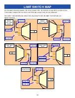
Page 35: ...EL HANDLE WILL STILL MOVE THE SOLENOID ASSEMBLY MAKE SURE TO REMOVE THE HANDLE WHEN SERVICING THE GAME OPEN ALL 5 DOOR AND PULL ALL 5 SWITCHES OUT DOOR OPEN MESSAGE STAYS ON A FAULTY DOOR SWITCH A5SW7000 B CHECK ALL SWITCH WIRES SEE THE NEXT PAGE C CHECK WIRE CRIMPS D CHECK THE CONNECTION ON THE I O BOARD SEE BELOW E REPLACE I O BOARD AACB1900 DOOR OPEN MESSAGE CLEARS A INDIVIDUALLY CHECK EACH SWI...

Page 36: ...CLOSED AND WILL FUNCTION NORMALLY WE DON T RECOMMEND DOING THIS UNLESS IT S NECESSARY FOR REPAIR OR MAINTENANCE FRONT LEFT SIDE DOOR AACE1604 AACE1600 AACE1619 FRONT RIGHT SIDE AACE1600 AACE1601 AACE1619 LEFT SIDE DOOR AACE1602 AACE1603 AACE1619 RIGHT SIDE DOOR AACE1602 AACE1601 AACE1619 BACK DOOR AACE1603 AACE1604 AACE1619 ...

Page 37: ...brate home position IMPORTANT ONLY SPIN WHEEL DOWNWARD Wheel encoder sensor AACB1901 is mounted so the top sensor reads the outside cut out notches Green LED Indicator Green LED Indicator The lower sensor reads the 1 home position notch on wheel How to Update Software The software is programmed onto a USB thumb drive dongle It pushes into any of the USB sockets on the motherboard To Change Softwar...

Page 38: ...r menu 4 Check if value on monitor matches wheel position pointer 5 Watch monitor as you manually turn the wheel down The wheel may have to go a full revolution so the game can find home position Spin the wheel downward by hand watch the display change as the wheel moves to the next score panel 5 Slowly rotate the wheel downward as it approaches a bonus section Watch the display as it turns to a 4...

Page 39: ...ghten Brake Loosen Brake Adjusting Wheel Brake Lift the threaded rod and spin nuts Clockwise to increase tension decrease wheel coast time Counter clockwise to decrease tension increase wheel coast time Re test after adjustment If customer inserts money during autospin and wheel coast is too long it may read the autospin as a player spin and give tickets for that autospin Make sure the wheel does ...

Page 40: ... LEFT SIDE DOOR 2 YOU WILL SEE A SPRING LOADED BOLT COMING UP FROM THE BRAKE 3 PULL THE BOLT UP AND SPIN THE LOCK NUT TO ADJUST YOU ONLY NEED TO DO 2 REVOLUTIONS TO ALTER THE PRESSURE TIGHTEN BRAKE DOWN LOOSEN BRAKE UP 4 RE SPIN TO CHECK THE BRAKE AFTER ADJUSTMENT ...

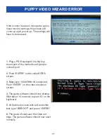
Page 41: ...purple colored port 2 Push ENTER on the initial XORG screen 3 Make sure 1024x768x16 is selected Push ENTER on the video resolution screen 4 The game software should now startup Wait about 10 seconds to push Q on the keyboard 5 At the black screen with red and white test type REBOOT and press ENTER 6 The game should save the video set tings The game software should now start normally PUPPY VIDEO WI...

Page 42: ...THERE IS A BOLT LOCK WASHER AND LOCK NUT UNDER THE SPEAKER BRACK ET REMOVE THE NUT AND BOLT TO RELEASE THE HANDLE THE HANDLE IS DESIGNED TO BE REMOVED FROM THE GAME THIS WILL ALLOW A TECHNICIAN TO WORK ON THE SOLENOID ASSEMBLY WITH A REDUCED CHANCE OF ACCIDENTAL INJURY ...

Page 43: ... ROLL TOP DESK FIG 2 3 REMOVE THE BACK DOOR THE TOP OF THE FRONT WINDOW CAN NOW BE REACHED 4 USE THE PROVIDED SWIFFERTM A5SWIFFER TO CLEAN ALL THE WINDOWS OR ANYWHERE THERE IS DUST AND DIRT BUILD UP FIG 3 5 ONCE DONE SLIDE THE FRONT WINDOW CLOSED AND SECURE THE 2 CLASPS FIG 1 6 CLEAN THE OUTSIDE OF THE WINDOWS WITH A CLEAN TOWEL AND WINDOW CLEANER ...

Page 44: ... 1 3 CHECK CONNECTION TO THE POWER SUPPLY FIG 2 4 CHECK THE POWER SUPPLY SWITCH THEN MAKE SURE THE VOLTAGE IS CORRECT FIG 2 5 CHECK POWER SUPPLY POWER SWITCH FIG 2 6 CHECK TO MAKE SURE THE FAN IS WORKING ON THE MOTHER BOARD FIG STEP 3 STEP 4 STEP 5 MAKE SURE FAN IS WORKING LED SHOULD BE ON CHECK FOR 12 VOLTS DC BETWEEN THE BLACK AND YELLOW WIRES ...

Page 45: ...0 AC voltage at cable going into Bill Acceptor from power strip If power is OK Clean Bill Acceptor path to make sure there is nothing jamming unit Check dipswitch settings on side of acceptor Make sure switch 8 is OFF for Always Enable ERROR CODES Note There are many different models and brands of Bill Acceptors that are used on redemption games Your Bill Acceptor may differ from the unit shown St...

Page 46: ...IGHTEN ANY NUTS THAT MAY HAVE COME LOOSE OVER TIME FIG 2 AND 3 3 ONCE ALL 6 BOLTS ARE TIGHTENEDM REATTACH THE ACRYLIC SHIELD FIG 1 IT IS IMPORTANT TO CHECK THE BOLTS HOLDING THE ARM BRACKET TO THE GAME CABINET PERIODICALLY TO ENSURE THEY STAY TIGHT FAILURE TO DO SO MAY CAUSE INJURY OR DAMAGE TO YOUR GAME FACTORY RECOMMENDATIONS SUGGEST YOU CHECK THESE BOLTS MONTHLY DEPENDING ON THE USAGE OF THE GA...

Page 47: ...stance please contact Baytek Games at 920 822 3951 Ext 1102 A5PICZ001 A5ME4157 A5PICZ001 A5BURU040 A5NULO080 A5BOPH301 A5RICZ010 A5ME4161 A5ME4171 A5ME4172 A5ME4174 A5BURU050 A5BOHH115 A5BOPH301 A5WASI010 A5NUHX060 A5ME4172 A5ME4156 A5RICZ010 A5SLZN010 A5ME4178 A5ME4224 A5ME4154 AASO4150 A5NULO050 ...

Page 48: ...ing Window Bracket A5ME4156 Metal Short Wheel Link A5ME4157 Metal Rocker Arm Brkt A5ME4159 Metal Top Front A5ME4161 Metal Handle Pivot Assy A5ME4163 Metal Clutch Mount A5ME4164 Metal Clutch Pivot Plate A5ME4165 Metal Clutch Swivel Plate A5ME4170 Metal Wheel Motor Bracket A5ME4171 Metal T Handle A5ME4172 Metal Handle Brkt A5ME4174 Metal Rocker Arm A5ME4177 Metal Frt Glass Brace Machined A5ME4178 Me...

Page 49: ...16 Cable Bbw Pro In Line Filter Cable AACE3219 P Cable Assy Ticket Tray AACE4000 Cable Assy Marquee Scooby Doo AACE4001 Cable Assy Minigen To Light Board AACE4002 Cable Assy Power Jumper To Lights AACE4003 Cable Assy Front Monitor Lights AACE8811 Cable Assy Speaker AAJP9092 Jumper Dba 12v 110v Mars Pyra AAPB2700 Pushbutton Assy AALS1701 Led Strip Front Accent AACB1900 SD Circuit Bd Assy Aux Board ...

Page 50: ...BDI030 A5CH1007 A5CORD12 A5CORD11 A5CORD 5 A5EB9000 A5EX1007 A5FI9010 A5GE4202 A5GE4203 A5LK2001 A5LK5002 A5ME4152 A5ME4153 A5ME4156 A5ME4157 A5ME4159 A5ME4161 A5ME4170 A5ME4171 A5ME4172 A5ME4180 A5ME4181 A5ME4182 A5ME4202 A5ME4205 AAMO4101 A5SP9107 A5ME4174 A5ME4177 A5ME4178 A5ME4179 ...

Page 51: ...T4101 A5VF4153 AACO1000 AASO4150 A5CEAU010 AACE1610 AACE1611 AACE1612 AACE1618 AACE1619 AACE1625 AACE1704 AACE1705 AACE1708 AACE1714 AACE1716 AACE8811 A5ME4224 A5SP1003 A5PL9097 A5SW7000 AAJP9092 AAPB2700 AALS1701 AACB1901 A5CA1005 W5TM4000 A5ME4183 A5ME4169 A5ME4184 AACB1900 SD AAMB9A FHD ...

Page 52: ... LOG If repairs are necessary it is good practice to keep a log of repairs done and parts ordered The chart below will assist you in tracking your game s maintenance DATE MAINTENANCE PERFORMED PARTS ORDERED INITIALS ...

Page 53: ...he quickest and provide you a valuable troubleshooting option Call our technicians to get recommendations for what you should keep on hand for spare parts Technical Support You are the best tool for troubleshooting Your abilities to understand the game and your skills to repair the game are invaluable to us If you need help you know you can call us It s not easy to diag nose a game remotely by pho...

Page 54: ... product or as a result of any unauthorized repairs or alterations The warranty does not apply if any serial number decal is altered defaced or removed from its original position Should you need your game serviced determine the serial number from the decal placed on the front of this manual or locate it on the back of the game Then contact our Service Department at 920 822 3951 or e mail service b...

Reviews: