24
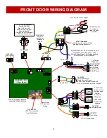
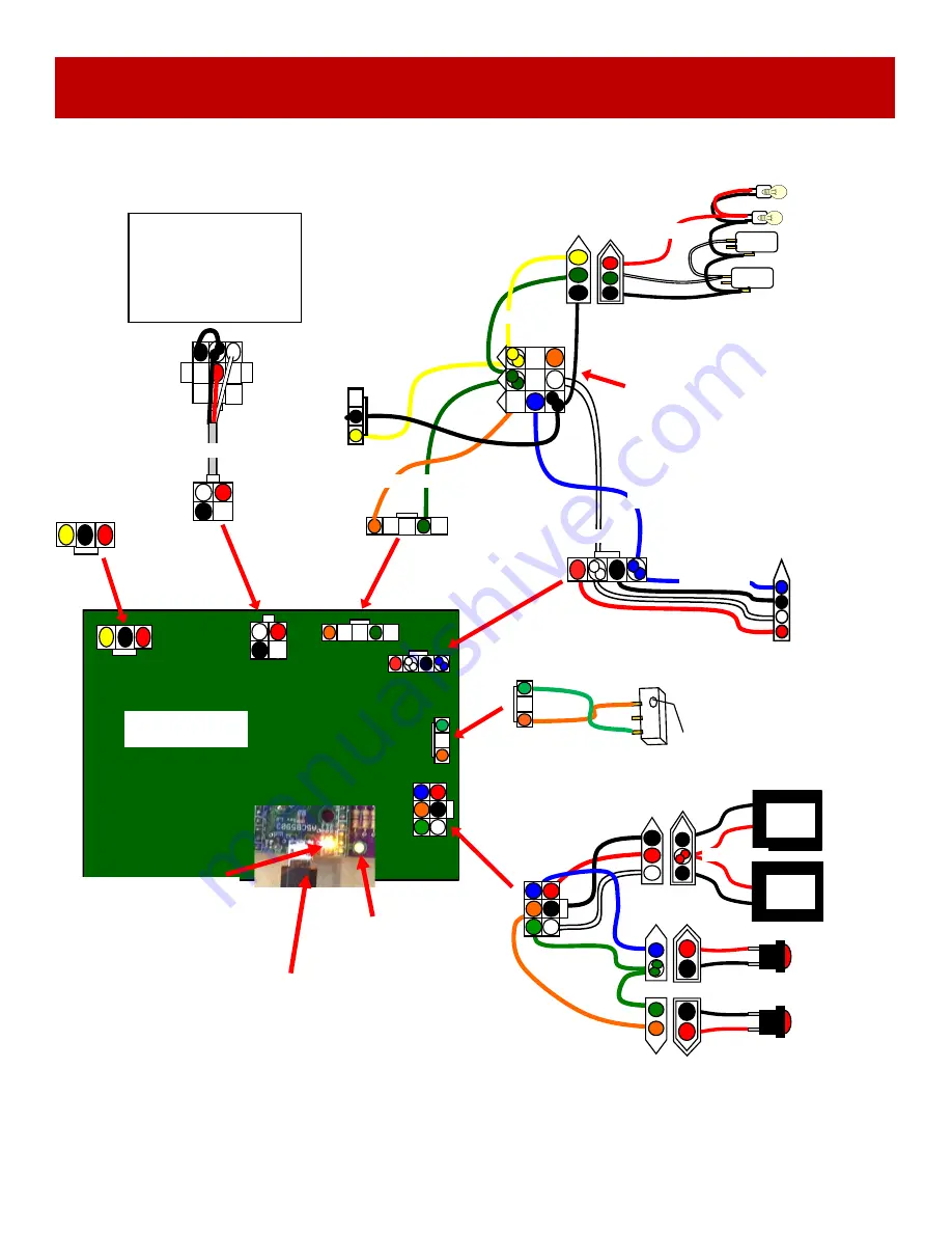
Green Power
LED should be
flashing
A5CBL5900
USB Communication
from Motherboard
AACB9605
-
CBL
I/O Aux Board
Red and yellow LEDs are
normally ON at all times.
Coin Switches and Lights
AACBL4A
-
DOORA
UCL Connector
Card Swipe system cable would be
plugged into this connector.
AACE26013
AACE26013
Power In
from Power
Distribution
Board
AACE26013
To Ticket
Dispenser
Part # A5TD1
Notch Signal
Com Ground
Enable Signal
12 Volt Power
AACE26013
AACE26013
4
-
5 VDC normally
on switches.
Goes to 0 when
activated.
Blue & Black Wires: 5 VDC when notch opto
is blocked. 0 VDC when sees a notch.
White & Black Wires: 5 VDC when enabled
and tickets are trying to dispense.
FRONT DOOR WIRING DIAGRAM
AASW200
Low Ticket Switch
Wired Normally Closed
0 VDC when no tickets on switch.
4
-
5 VDC when tickets on top of switch.
AACE26013
AACE26008
To 12 Volt Bill Acceptor
Part # A5AC9101
Red is 12 Volts DC
White is Coin Up Signal
Black is Ground
Normally 4
-
5 VDC between
white and black wires
AACE26014
Power in from
Power Dist Bd
AAPB2700
Menu Button
Game
Counter
Ticket
Counter
AACO1020
AACE26012
4
-
5 VDC on switches
Meters
receive 12
VDC pulse
AAPB2700
Menu Select Button
Game meter
clicks at start
of game.
Ticket meter
clicks as tickets
are dispensed.

