background image

237    Owner’s Manual 

Supplement

Chapter 6: Plumbing

33

Freshwater System Winterization

1. Turn Off the water heater breaker switch.

NOTE: Tag or Mark the water heater breaker switch to prevent it from being turned On while the water heater 
tank is empty.

2. Turn On the freshwater pump switch.
3. Open all of the faucets and showers and let the freshwater system drain completely.
4. Turn Off the freshwater pump switch.

All of the remaining water must be removed from the water lines. There are two ways to remove the remaining water 
from the lines:

Compressed Air

Gravity Draining

Compressed Air

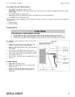
You must have an air compressor with an air hose and 
an air nozzle.

1. Remove the water line from the outlet side of the 

freshwater pump (opposite side from filter).

2. Open the faucet that is furthest away from the fresh-

water pump.

3. Place the air nozzle against the end of the just 

removed water line and blow air through the system.

4. When water stops coming out of the faucet, stop the 

air and Close the faucet.

5. One at a time, repeat this process on all faucets and 

showers.

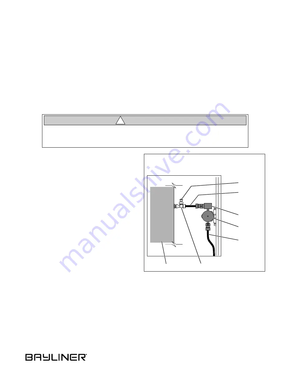
Gravity Draining

1. Open all faucets and showers.
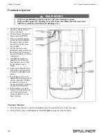
2. Remove the drain plug from the tee fitting on the 

freshwater tank.

3. When the water has stopped draining from the 

freshwater tank and the water lines, replace the 
drain plug.

FRESHWATER SYSTEM DAMAGE HAZARD!

A faucet MUST be Open when compressed air is blown through the freshwater system.

NEVER blow compressed air through the water system when ALL of the faucets are Closed.

CAUTI ON

!

TYPICAL VIEW

NOTE: LOCATION OF TEE FITTING
& DRAIN PLUG MAY VARY

FRESHWATER TANK

FILTER

FRESHWATER

OUTLET SIDE

WATER LINE

INLET SIDE

WATER LINE

DRAIN PLUG

TEE FITTING

PUMP

Summary of Contents for 237 Deckboat

Page 1: ......

Page 2: ......

Page 3: ...in this document or from the use of information contained herein Due to our commitment to product improvement Bayliner reserves the right to make changes in the product design specifications and equi...

Page 4: ...s 10 Helm 11 Component Locations 12 Chapter 3 Propulsion Related Systems Engine 22 Bilge Blower System 22 Fuel System 23 Fuel Fill Vent 23 Fuel Filters 24 Anti siphon Valve 24 Quick Oil Drain System 2...

Page 5: ...eds Tables Stowage Areas 42 Bow Sunlounge Conversion 43 Removable Fishing Seats If Equipped 45 Chapter 10 Lights Care Maintenance 46 Interior Exterior Lights 46 Navigation Lights 46 Chapter 11 Electri...

Page 6: ...alerts you to hazards or unsafe practices which COULD result in severe personal injury or death if the warning is ignored WARNING This box alerts you to hazards or unsafe practices which COULD result...

Page 7: ...copy of the Limited Warranty please contact your Bayliner dealer or call 360 435 8957 for a copy Boating Experience If this is your first boat or if you are changing to a type of boat you are not fami...

Page 8: ...his supplement is included in your owner s packet Propeller Keep the propeller in good repair and at the correct pitch for your particular situation A slightly bent or nicked propeller will adversely...

Page 9: ...on its hull bottom This will detract from your boat s beauty greatly affect its performance and may damage the gel coat Periodically haul your boat out of the water and scrub the hull bottom with a br...

Page 10: ...m the back deck or swim platform while the engine is running Teak surfing dragging or water skiing within 20 feet of a moving watercraft can be fatal DANGER DANGER PERSONAL SAFETY HAZARD ALWAYS secure...

Page 11: ...e fatal Breathing CO blocks the ability of your blood to carry oxygen The effects are cumulative Even low levels of exposure can result in injury or death Factors that Increase the Effects of CO Poiso...

Page 12: ...ough CO can be present without the smell of exhaust fumes if exhaust fumes are detected on your boat take immediate action to dissipate these fumes Treat symptoms of seasickness as possible CO poisoni...

Page 13: ...place if worn Make sure cooling systems are in working condition Inspect all metallic exhaust components for cracking rusting leaking or loosening Make sure they check the cylinder head gasket exhaust...

Page 14: ...Chapter 1 Welcome Aboard 237 Owner s Manual Supplement 8 Warning Labels...

Page 15: ...9 237 Owner s Manual Supplement Chapter 2 Locations Exterior Views Hull Views...

Page 16: ...Chapter 2 Locations 237 Owner s Manual Supplement 10 Deck Views...

Page 17: ...237 Owner s Manual Supplement Chapter 2 Locations 11 Helm ACTUAL LAYOUT MAY VARY DEPENDING ON ENGINE AND ACCESSORY OPTIONS NOTE TYPICAL HELM LAYOUT SHOWN...

Page 18: ...s 237 Owner s Manual Supplement 12 Component Locations 12 Volt DC Accessory Outlets 2 Total One is located at the helm One is located on the starboard aft corner of the deck 12 Volt DC Fuse Block Loca...

Page 19: ...g Motor Circuit Breaker If Equipped There are two possible locations Located under the star board bow seat cushion or Located inside the port cockpit hatch behind the trash can 12 Volt DC Trolling Mot...

Page 20: ...r s Manual Supplement 14 Battery Located in the port aft corner of the engine compartment Bilge Pumps The aft bilge pump is located in the engine compartment bilge The forward bilge pump is located in...

Page 21: ...Owner s Manual Supplement Chapter 2 Locations 15 Blower Switch Located at the helm Depth Finder Transducer Located in the engine com partment bilge Depth Finder Trans ducer If Equipped Located on the...

Page 22: ...237 Owner s Manual Supplement 16 Freshwater Fill Deck Fitting marked WATER Located on the port deck Freshwater Pump Located inside the port cockpit hatch behind the trash can Freshwater Pump Switch L...

Page 23: ...2 Locations 17 Freshwater Tank Located inside the port cockpit hatch behind the trash can Fuel Fill Deck Fitting marked GAS Located on the starboard aft corner of the deck Fuel Tank Located in the fo...

Page 24: ...trol Valve If Equipped Located inside the livewell Access by removing the port bow seat cush ion and lifting the livewell hatch Livewell Pump Switch If Equipped Located at the helm Livewell Seawater I...

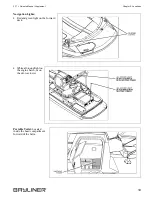
Page 25: ...ement Chapter 2 Locations 19 Navigation Lights Red and green light on the forward deck White all round light on the engine hatch or on the ski tow tower Portable Toilet Located inside the head compart...

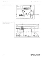
Page 26: ...Chapter 2 Locations 237 Owner s Manual Supplement 20 Transom Shower Located on the starboard aft corner of the deck Trim Tilt Pump Located in the starboard aft corner of the engine compartment...

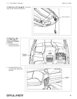
Page 27: ...ions 21 Trolling Motor If Equipped Located on the port side of the forward deck Trolling Motor Bat tery If Equipped There are 2 possible locations Located inside the forward floor hatch Located inside...

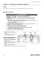
Page 28: ...when running your boat below cruising speed FIRE and EXPLOSION HAZARD Fuel vapors can explode BEFORE starting the engine 1 Check the bilge areas for fuel vapors or leaking fuel If you see leaking fue...

Page 29: ...PEN FLAME HAZARD It is very important that the fuel system be inspected thoroughly the first time it is filled and at each subsequent filling The fueling instructions in the Sport Boat Owner s Manual...

Page 30: ...hat help prevent fungus or other buildup in your fuel tank Anti siphon Valve The anti siphon valve is a vital fuel system part If the fuel line ruptures this valve will prevent the fuel from siphoning...

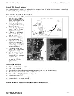
Page 31: ...stop clamp G so that no more than 12 inches of hose including the oil drain plug can extend out of the bilge drain A 7 Clip the bilge plug s draw cord C back to the oil drain plug s draw cord D 8 Push...

Page 32: ...s Cleaning the Gauges Gauge Fogging Moisture may occasionally find its way into the gauges causing lens fogging Turning On the gauge lights will help dry the lenses Fogging will not harm the gauges Ra...

Page 33: ...use the depth finder as a navigational aid to prevent collision grounding boat damage or personal injury When your boat is moving submerged objects will NOT be seen until they are already under your...

Page 34: ...hould work even when your boat is unattended Bilge Pump Testing The bilge pumps are vital to the safety of your boat Test the bilge pumps often 1 One at a time turn On each bilge pump switch at the he...

Page 35: ...in place Autofloat Switches The autofloat switches turn the bilge pumps On when water rises above a preset level Test each autofloat switch often Autofloat switch testing 1 Lift the float switch test...

Page 36: ...eaning and maintenance information FLOODING and SWAMPING HAZARD Close the seacock s when leaving your boat unattended for any length of time If a seacock is left open a hose failure could flood the bi...

Page 37: ...ter does not pump into the tank possi ble causes are The intake seacock is Closed A hose is collapsed or there is clogging debris in the system The livewell fuse is blown FLOODING and SWAMPING HAZARD...

Page 38: ...he fresh water filter often the filter is located on the freshwater pump If your boat is to be left unattended for a long period of time pump the freshwa ter tank dry to prevent stored water from beco...

Page 39: ...e side from filter 2 Open the faucet that is furthest away from the fresh water pump 3 Place the air nozzle against the end of the just removed water line and blow air through the system 4 When water...

Page 40: ...cockpit sink drain is above the waterline and is gravity drained overboard Portable Toilet Read the manufacturer s operating instructions before using the portable toilet Portable Toilet Pump out If...

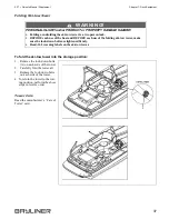
Page 41: ...the tow rope as shown in the photo PERSONAL INJURY and or PRODUCT or PROPERTY DAMAGE HAZARD NEVER lift your boat using the bow stern eyes or the cleats WARNING PERSONAL INJURY and or PRODUCT or PROPER...

Page 42: ...the boat and BEFORE each use of the folding ski tow tower make sure the lock down bolts are tightened firmly ONLY tow water skis wakeboards or kneeboards Do NOT exceed the MAXIMUM tow weight of 600 po...

Page 43: ...h side of the tower To return the tower to the tow ing position perform the above steps in reverse order Tower Care Read the manufacturer s Care of Tower card PERSONAL INJURY and or PRODUCT or PROPERT...

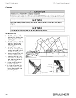
Page 44: ...braces H forward 5 Insert the end eyes of the forward braces H into the deck hinges I and insert the securing pins The jaw slides should not need to be adjusted If you decide to adjust the jaw slide p...

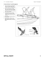
Page 45: ...f the aft braces C into the deck hinges D and insert the securing pins 3 Pull the secondary bow E and braces F forward 4 Insert the end eyes of the for ward braces F into the deck hinges G and insert...

Page 46: ...e waterproof finish of the fabric and may also decrease the life of the polyester thread used in the canvas Reapply a water repellent treatment as needed Method 1 1 Add 1 8 cup 2 oz of non chlorine bl...

Page 47: ...s Manual Supplement Chapter 8 Entertainment Systems Audio Equipment Read the manufacturer s instruction manual before using the audio equipment AM radio reception may be impaired when the engine is ru...

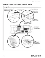
Page 48: ...BOARDS FORWARD TO DODGE CUPHOLDERS SECURE BOARDS CUSHION WITH STRAPS ALSO STOW AFT CASTING SEAT IN THIS COMPARTMENT STOW FORWARD STOW ADDITIONAL FILLER CUSHIONS FORWARD OF FILLER BOARDS CASTING SEATS...

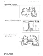
Page 49: ...nversion 1 Remove the table A and the table leg B 2 Securely store the table A and the table leg B in the storage area inside the head compartment 3 Unfold the support leg C of the for ward filler boa...

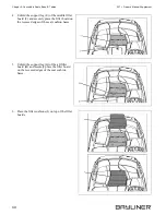
Page 50: ...he middle filler board F and securely place the filler board on the recessed edges of the seat cushion bases 5 Unfold the support leg G of the aft filler board H and securely place the filler board on...

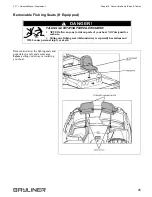
Page 51: ...fishing seats and pedestals in a safe and secure area before getting underway or trailering your boat FALLING and ROTATING PROPELLER HAZARD NEVER allow anyone to ride on parts of your boat NOT design...

Page 52: ...required 4 The bulb base may be corroded clean the base and coat it with non conductive electrical lubricant Interior Exterior Lights The lights are powered by your boat s 12 volt DC system The batte...

Page 53: ...lectrical devices 1 Check the bilge areas for fuel vapors or leaking fuel If you see leaking fuel or smell fuel vapors a Do NOT start the engine do NOT turn On any electrical devices extinguish ALL ci...

Page 54: ...h one or more 12 volt DC accessory outlets The outlet s can be used with any 12 volt device which draws 10 amps or less Each 12 volt DC accessory outlet is protected by a 10 amp fuse on the fuse block...

Page 55: ...237 Owner s Manual Supplement Chapter 11 Electrical System 49 Electrical Routings 12 Volt DC Hull Harness...

Page 56: ...Chapter 11 Electrical System 237 Owner s Manual Supplement 50 12 Volt DC Deck Harness...

Page 57: ...237 Owner s Manual Supplement Chapter 11 Electrical System 51 12 Volt DC Digital Depth Finder Trolling Motor Harness If Equipped...

Page 58: ...Chapter 11 Electrical System 237 Owner s Manual Supplement 52 12 Volt DC Fish Pack Harness If Equipped Battery Cable Routings...

Page 59: ...ber Engine Serial Number Oil Type SAE Quarts per Engine Filter Type Propeller Manufacturer Pitch Model Number Key Numbers Ignition Other Electronics Manufacturer Model Name Number Serial Number Manufa...

Page 60: ...ration Documentation Number Length Make Type Hull Color Trim Color Fuel Capacity Engine Type Number of Engines Distinguishing Features Distinguishing Features Operator of Boat Full Name Male or Female...

Page 61: ...e Stopover 1 Arrive No Later Than Date Arrive No Later Than Time Stopover 2 Arrive No Later Than Date Arrive No Later Than Time Stopover 3 Arrive No Later Than Date Arrive No Later Than Time Stopover...

Page 62: ...Owner s Notes...

Page 63: ......

Page 64: ...Part Number 1838571 Bayliner P O Box 9029 Everett WA 98206 360 435 5571...

Reviews: