Chapter 2: Features / Systems
285 • Owner’s Manual Supplement
18
Battery Switch
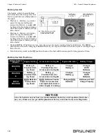
The battery switch (located behind
the helm seat in the storage area) has
four (4) positions (see photograph on
the right);
•
Position 1 - Battery 1 provides
power for engine starting and
accessories. Battery 1 (only) will
be charged by the engine alternator
when the engine is running at high
idle or faster.
•
Position 2 - Battery 2 provides
power for engine starting and
accessories. Battery 2 (only) will
be charged by the engine alternator
when the engine is running at high
idle or faster.
•
Position BOTH - If batteries are low, provides power for engine starting from both batteries. The BOTH
position also allows the charging of both batteries by the engine alternator when the engine is running at high
idle or faster.
•
Turn the battery switch to the Off position whenever the boat will be unoccupied for long periods of time.
Battery Switch Positions
Battery Switch
Position
Engine Starting
Accessories and Lights
Engine Alternator
Battery Charger
POSITION
1
Battery 1
Provides Start-
ing Power
Battery 1
Provides Power for
Accessories and Lights
Charges
Battery 1
Charges
BOTH
Batteries
POSITION
2
Battery 2
Provides Start-
ing Power
Battery 2
Provides Power for
Accessories and Lights
Charges
Battery 2
Charges
BOTH
Batteries
BOTH
POSITION
BOTH Batteries
Provide Start-
ing Power
BOTH Batteries Provide
Power for Accessories
and Lights (not advised
unless engine is running)
Charges BOTH
Batteries
Batteries will NOT
Charge Properly
BATTERY SWITCH LOCATED
IN AFT DECK STORAGE
AREA ON PORT SIDE
POSITION "1"
"OFF"
BATTERY "1"
ACTIVATES
POSITION
POSITION "BOTH"
BATTERIES
ACTIVATES BOTH
POSITION "2"
BATTERY "2"
ACTIVATES
AFT DECK
STORAGE
BATTERY SWITCH
Since the batteries on your boat were dealer-installed, the battery switch positions listed above
may vary. Make sure you get a full explanation of battery switch use from your selling dealer.
NOTI C E
Summary of Contents for 285 Cruiser
Page 1: ......
Page 2: ......
Page 51: ...285 Owner s Manual Supplement Chapter 4 Wiring Diagrams 45 AC Electrical System Dual Dockside...
Page 52: ...Chapter 4 Wiring Diagrams 285 Owner s Manual Supplement 46 Gas Engine Electrical System...
Page 53: ...285 Owner s Manual Supplement Chapter 4 Wiring Diagrams 47 Diesel Engine Electrical System...
Page 57: ...Owner s Notes...
Page 58: ...Owner s Notes...
Page 59: ......
Page 60: ...Part Number 1700674 Bayliner P O Box 9029 Everett WA 98206 360 435 5571...


