285 • Owner’s Manual Supplement
Chapter 2: Features / Systems
21
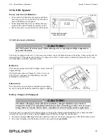
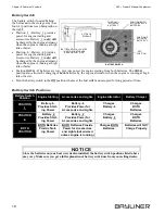
Connecting To Shore Power
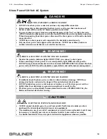
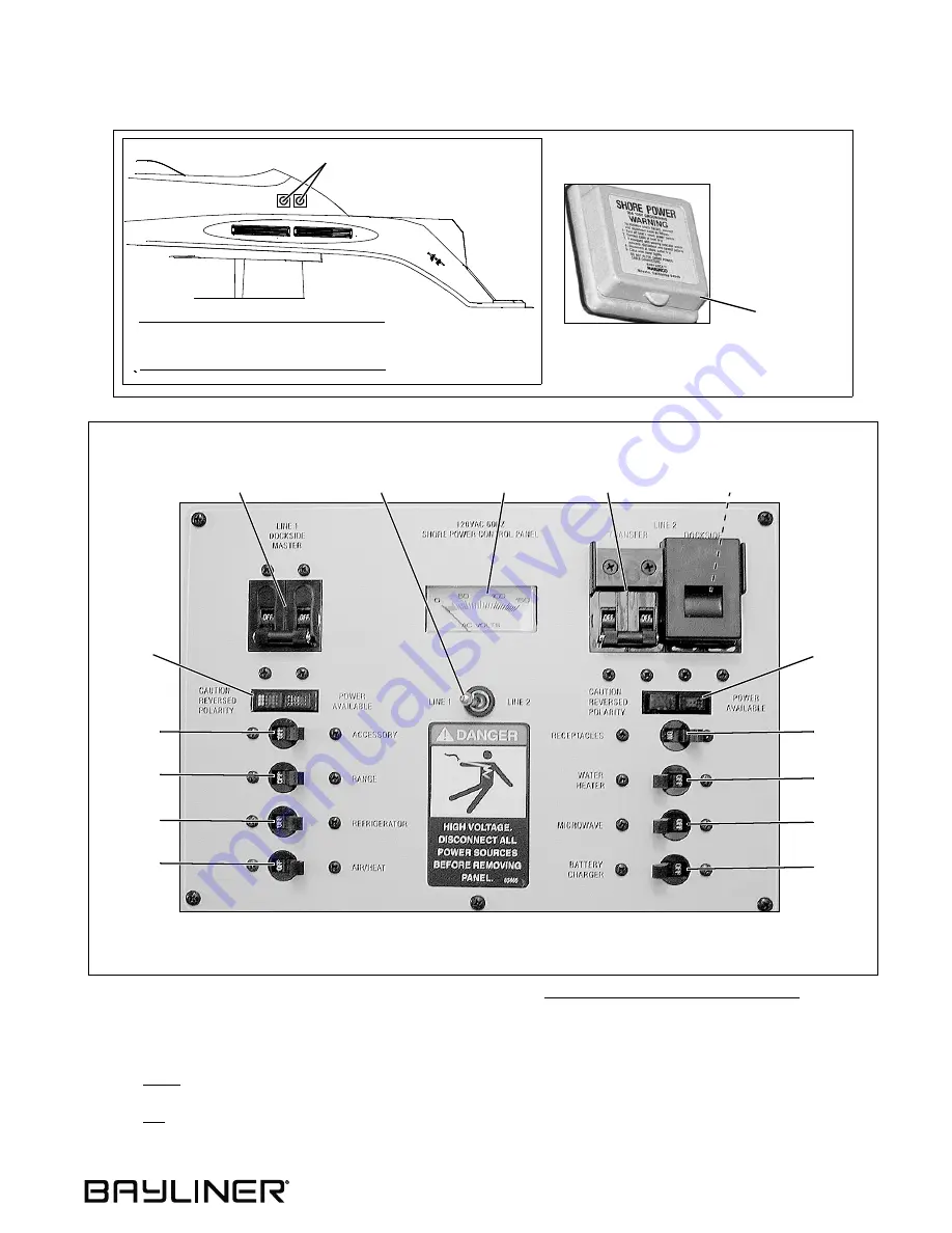
1. Review all hazard information at the beginning of this section, Shore Power/120V/60Hz AC System.
2. Turn Off all breakers and switches on the AC master panel.
3. Attach the shore power cord to the boat inlet first then to the dockside outlet.
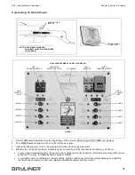
4. Monitor the AC panel’s polarity indicator lights, located below the line master breaker(s), as follows:
•
A green light illuminating after the power cord is plugged into the dockside outlet indicates acceptable electri-
cal power. You may turn On the master breaker switch.
•
A red light, however, indicates reversed polarity, which could cause electrical system damage and possibly
electrical shock injuries. In this case, do not turn On the master breaker switch.
TYPICAL SHORE
POWER INLET
SHORE POWER
INLET(S)
SINGLE INLET STANDARD
DUAL INLETS WITH AIR CONDITIONER
NOTE:
(IF EQUIPPED)
FIGURE 1
15 AMPS
DUAL SHORE POWER AC PANEL (IF EQUIPPED)
LINE 2
TRANSFER
LINE 1
DOCKSIDE MASTER
15 AMPS
15 AMPS
15 AMPS
10 AMPS
20 AMPS
5 AMPS
25 AMPS
LINE 2
DOCKSIDE MASTER
LINE 1
POLARITY
LIGHT
LINE 2
POLARITY
LIGHT
VOLTMETER
SELECTOR SWITCH
VOLTMETER
Summary of Contents for 285 Cruiser
Page 1: ......
Page 2: ......
Page 51: ...285 Owner s Manual Supplement Chapter 4 Wiring Diagrams 45 AC Electrical System Dual Dockside...
Page 52: ...Chapter 4 Wiring Diagrams 285 Owner s Manual Supplement 46 Gas Engine Electrical System...
Page 53: ...285 Owner s Manual Supplement Chapter 4 Wiring Diagrams 47 Diesel Engine Electrical System...
Page 57: ...Owner s Notes...
Page 58: ...Owner s Notes...
Page 59: ......
Page 60: ...Part Number 1700674 Bayliner P O Box 9029 Everett WA 98206 360 435 5571...

