background image

53

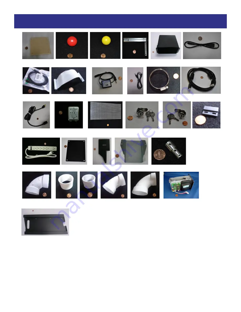
PARTS LIST

Parts Pictures 

         A5AC1004                   A5BA5802 

          A5BA3201                 A5BK9999                   A5CB2050 

            A5CBL5900     

      A5CBL6500           A5CBL-RBN40-1 

            A5CE2300              A5CEAU010 

A5CL6500 

           A5CORD36  

        A5CORD5                 A5FI9010 

          A5LD1052   

       A5LK2001 


A5LK5002  

   A5MA9700

           A5OU1000                       A5PL8900 

     A5ME4180             A5ME4182                      A5ME5180 

        A5PV6503              A5PV6504       A5PV6505 

    A5PV6506 

        A5PV6507                          A5TD1 


               A5TT4101 


Summary of Contents for SQUIGGLE

Page 1: ...1 ...

Page 2: ...baytekgames com SALES P 920 822 3951 F 920 822 8936 E sales baytekgames com All games are proudly manufactured at our factory in Pulaski Wisconsin USA JOIN OUR SERVICE FIRST NETWORK This free service is intended to keep you up to date on the latest game information early notification of parts specials pertinent technical bulle tins updates on retro fit parts software upgrades and much more Log on ...

Page 3: ...CH SETTINGS 7 SETUP GUIDE 8 13 MAIN MENU FUNCTIONS 14 VOLUME AND ATTRACT 15 GAME SETTINGS 16 PAYOUT MENU 17 TICKET PATTERNS 18 DATE LOCATION 19 STATISTICS 20 DIAGNOSTICS 21 WIRING DIAGRAMS 22 30 TROUBLESHOOTING 31 39 DIAGNOSTICS 40 41 HOW TO 42 48 TUBE DIAGRAMS 49 50 PARTS LIST 51 55 DECAL DIAGRAM 56 MAINTENANCE LOG 57 TECHNICAL SUPPORT 58 WARRANTY 59 ...

Page 4: ... through this manual and be sure to contact our factory if you have any questions or would like some more information Thank you for your purchase Your business is important to us and we hope you enjoy this game as much as we do Your Friends at Bay Tek Games GAME INSPECTION Inspect the game for any damaged loose or missing parts If damage is found please contact your freight carrier first Then cont...

Page 5: ...HOW TO PLAY Try to time the yellow ball drop where the bonus spot is Wait for the red balls to drop Hit the button when you want the yellow ball to drop Earn tickets based on where the yellow ball landed ...

Page 6: ...of flammable subtances can cause sever burns or serious injury Always use NON FLAMMABLE solvents for cleaning DO NOT use gasoline kerosene or thinners CAUTION Lifting heavy objects can cause back neck or other injuries Be sure adequate lifting and moving devices are available when unloading unpacking and moving this game ATTENTION Be sure the electrical power matches the game requirements See the ...

Page 7: ...7 DIP SWITCH SETTINGS The dip switch bank is located on 2 small sensor control boards behind the lower service panel in the back of the game Bottom sensor settings Top sensor settings ...

Page 8: ...8 SETUP GUIDE Lay the top playfield on the ground Lay the contol panel portion of the game down Match bars with the fitting hole on each side and slide the Playfield to the control panel ...

Page 9: ...9 SETUP GUIDE CONT Stand the game up vertically Install 1 4 bolts in top piece by the middle tube Hammer 3 bolts into each side and tighten to secure the top half of game to the bottom half ...

Page 10: ...10 SETUP GUIDE CONT All cords will be color coded except the next two cords addressed Link the green and yellow cord 6535 to 6536 Place 18 red balls in the left tube ...

Page 11: ...11 SETUP GUIDE CONT Plug 6528 into the bottom motor Connect 6510 black to 6424 black Connect 6500 1 yellow to 6500 2 yellow Connect 6512 plugs into bottom motor ...

Page 12: ...12 Connect 6513 gold to 6520 2 gold Connect 6521 brown to 6503 brown Connect 6507 pink to 6519 pink Connect 6507 white to 6524 white SETUP GUIDE CONT ...

Page 13: ...13 6510 red to 6519 red Once all cables are hooked up install piping Install the bigger pipe on the left side of the game and install the smaller tube in the middle SETUP GUIDE CONT ...

Page 14: ...Menu Scroll through the options with the MENU button Make your selections with the MENU SELECT button CLEAR TIX CRED Press the MENU SELECT button 3 times to clear tickets and credits owed RESET FACTORY DEFAULTS Press MENU SELECT button 3 times to reset all settings to factory defaults MUTE OPTION ON OFF ...

Page 15: ... OF 5 100 DEFAULT 40 MUSIC VOLUME 0 TO INC OF 5 100 DEFAULT 40 EFFECTS VOLUME 0 TO INC OF 5 100 DEFAULT 40 VOICE VOLUME 0 TO INC OF 5 100 DEFAULT 40 BONUS VOLUME 0 TO INC OF 5 100 DEFAULT 40 ATTRACT TIMING 0 1 2 3 4 5 6 7 8 9 10 VOLUME ATTRACT SETTINGS ...

Page 16: ...OW 1CR TIX Gameplay starts with single pulse to coin input no tickets rewarded ENTERTAIN ONLY Same as show mode will change in future version MARQUEE MODE ALTERNATING will alternate between BONUS TICKETS or POINT based on what Game Mode payout is set to STATIC BONUS will always be displayed RED BLOWER TIME 2 0s TO inc of 2 4 0s DEFAULT 3 0s BALL TUBE BRIGHTNESS 0 10 20 30 40 50 60 70 80 90 100 MAX...

Page 17: ...ENABLED DISABLED PAPER TICKET VALUE 1 2 1 FIXED TICKETS 0 TO inc of 1 20 MERCY TICKETS 0 1 2 3 4 5 6 7 8 9 10 MERCY REPLAY ENABLED DISABLED MIN BONUS VALUE 50 TO inc of 25 1000 DEFAULT 300 BONUS INCREMENT 0 TO inc of 5 25 MAX BONUS VALUES 50 TO 1000 DEFAULT 1000 TICKET PATTERN 1 TO 7 ...

Page 18: ...14 34 20 20 40 4 4 8 14 34 20 50 80 8 8 14 32 50 20 12 30 2 2 6 12 26 20 12 30 2 2 6 12 26 20 300 400 200 50 300 300 300 300 12 30 2 2 6 12 26 20 12 30 2 2 6 12 26 20 50 80 8 8 14 32 50 20 20 40 4 4 8 14 34 20 20 40 4 4 8 14 34 20 30 60 6 6 10 18 40 20 12 30 2 2 6 12 26 20 12 30 2 2 6 12 26 20 12 30 2 2 4 8 14 20 COST PER PLAY 1 00 2 00 0 50 0 50 0 75 1 00 1 50 1 00 AVG TICKETS PER PLAY 32 34 60 6...

Page 19: ...ocal timezone This will be used to set the clock when an Ethernet cable is connected to the game It is not necessary to have an Ethernet cable connected for proper game operation DATE The current date automatically set if the game is connected to a network It is not necessary for the clock to be set for proper game operation TIME The current time of day automatically set if the game is connected t...

Page 20: ...e last reset In those cases the ball is auto matically dropped TOTAL BONUS WINNERS Number of game in which the player won the bonus since last reset AVERAGE TICKETS Quotient of total number of tickets divided by the total number of games since last reset MERCY REPLAYS Number of free games given to players who on their first attempt land the ball on the very top or very bottom of the tube since las...

Page 21: ...tic for a time when the blowers are started until the balls have fallen into the tube SENSOR ID select the top or bottom ball color sensor to use for the above Red Green Blue display TICKET DISPENSER Pressing the Menu Select button with this item highlighted will send the signal to dispense one ticket to the ticket dispenser RELEASE YELLOW BALL Pressing the Menu Select button with this item highli...

Page 22: ... Raspberry Pi AACE6525 AACE6525 AACE6528 AACE6529 AAFA6500 Cooling Fan A5CORD5 Power In Cord from wall Note The 220 Volt AC version of this blower is part AABL6501 Yellow Balls Blower AABL6505 Red Balls Blower 120 VAC 12 Ohms AACE6515 Blower Signal from I O Aux Board AACB9601 SQ I O Aux Board AABD5029 A AC Driver Board AACB5156 Power Dist Board AC Power comes with TV Power Supply A5PS1013 Blank Pl...

Page 23: ...n pushed Drop Button Assembly AAPB6500 A5MA9700 Magnet Riveted On AACE6544 Switch w Cable A5SP9700 Spring 4 per Button UCL Universal Card Link Connector for Card Swipe Systems Orange is Inhibit wire White is the Ticket Enable Black is Ground Blue is the Ticket Notch Green is Coin Signal Red is 12 Volts DC AACE6517 AACE6517 Game Counter Ticket Counter AACO1020 Menu Select AAPB2700 Menu Button AAPB2...

Page 24: ...n running AAMO6500 Right Motor Ohms vary from 7 to 220 12 Volts DC when running AACB9600 Audio Amplifier AACE6502 AACE6506 AACB6502 RGB Control Lights 12 5 VOLT FROM POWER DISTRIBUTION BOARD AACE6507 5 Volts DC to Top Outside LED s To AACE6519 Outside LED s Pink Connector AACE6507 5 Volts DC to Middle Track LED s To AACE6524 Middle Track LED s White Connector No Color Connector AACE6533 5 VDC from...

Page 25: ...of the game Bottom of the game Brown Connectors AACE6521 AACE6548 AACB4051 2 Marquee Board above the game Top of the game AACB9601 SQ I O Aux Board AACE6516 AACE6522 AASO6500 Ball Stack Solenoid 4 Ohms AABL6500 12V yellow Ball blower 0 8 Ohms AACB6503 Current Limiter AACE6515 AACE6518 To AC Driver Board Controlling red balls blower AACE6526 AACE6531 AACE6532 AASO6501 Ball Sort Solenoid 4 Ohms AAMB...

Page 26: ...ttom of the game Not Used Green Connectors AACE6507 5 Volts 5 Volts DC from Power Distribution Board Pink Connectors AACE6507 5 Volts 5 Volts DC from Power Distribution Board AACE6511 AACE6510 AACE6519 Right Outside Edge LED s AACB9601 SQ I O Aux Board Blue Connectors Red Connectors Not Used AACE6524 Inside and outside of inside track LED s WIRING DIAGRAM ...

Page 27: ...ACE6509 Silver Connectors AACE6538 Inside of right outside track LED s AACE6539 Inside of left outside track LED s Top of the game Bottom of the game AACE6556 AACE6555 Red Ball Drop Area LED s AACE6541 Drop Button LED Board AACE6540 Outside of right outside track LED s Purple Connectors AACE6556 Blue Connectors AACE6550 AACE6509 AACE6509 No Color Connector No Color Connector Gold Connectors Orange...

Page 28: ...L5900 USB Cable to RGB Control Bd Speaker AACE8811 3 3 Ohms AACE6505 AACE6505 Speaker AACE8811 3 3 Ohms A5CB6501 Color Control Board A5CB6501 Color Control Board A5CB6500 Color Sensor AACE6549 AACE6549 A5CBL6500 USB cables for color sensors White LED s on front of board are ON when color sensor is ready to read balls Red LED on board will flash when color sensor is seeing a ball A5CBL RBN40 1 Ribb...

Page 29: ... Main Board Game main board SD Card location AAMBRPI SQ M Rasp Pi Marquee Marquee Sign main board SD card location To remove Push gently into board and let it pop back out remove from board To install Push gently into board until it clicks SD Card part number is AASD0008A please specify game location when ordering UCL Universal Card Link Connector for Card Swipe Systems Orange is Inhibit wire Whit...

Page 30: ...cket counter processed on 9601 White is Game counter Processed on 9601 Red is 12 VDC LED lights Red is 5 VDC White is signal processed on 9601 Black is Ground Ball Sort Solenoid Red is 12 VDC Black is FET5 on board Red Balls Blower Red is 12 VDC Black is FET3 on board Yellow Ball Solenoid Red is 12 VDC Black is FET1 on board Yellow Ball Blower Red is 12 VDC Black is FET2 on board Ball Stack Soleno...

Page 31: ...0 Drop Button LED s not working Power goes through RGB Control Light Board LED strip faulty Faulty Cable Faulty RGB Control Light Board Open front door and examine circuit board with LED s Replace if needed AACE6541 Check cables from LED board to RGB Control Board AACE6541 AACE6504 Swap cables to a different socket on the board Replace RGB Board if needed Part AACB6502 Drop Yellow Ball center ball...

Page 32: ... s Examine LED strip Replace LED strip if needed AACB6519 Refer to How to Replace LED Lights in Playfield Replace I O Aux Board Part AACB9601 SQ Inside middle track color LED s not working Power goes through I O Aux Board Faulty Cable Extra 12 Volts to LED LED strip faulty Faulty I O Aux Bd Check cables from LED strip to I O Aux Board AACE6524 AACE6510 Make sure 12 volts is being back fed through ...

Page 33: ...h compressed air and if necessary wipe sensor with isopropyl alcohol on a cotton swab Flip tickets and load upside down to have largest cut notch toward opto sensor Replace dispenser with spare working dispenser A5TD1 If the notch signal is not being seen replace the I O Aux Board AACB9601 SQ If the Enable signal is not present replace the Raspberry Pi AAMBRPI SQ Tickets dispensing all the time Ti...

Page 34: ...s DC power in Check A5PS9600 plugged into power strip Replace Raspberry Pi AAMBRPI SQ AAMBRPI SQ Rasp Pi Main Board Red balls are sticking in the playfield area Static in the playfield Ball jam in the playfield There is a metal plate behind the top row of pins that will pull static from the balls as they pass by Make sure metal plate is grounded to game ground and wall ground Balls may get stuck o...

Page 35: ... wiring Signals are processed on Rasp Pi Wait until balls are being sorted from tube to press menu button for right timing Replace button if problem stays with button AAPB2700 Inspect crimp to ensure good connection Check connections from menu buttons to main board Check continuity on AAPB2700 AACE6514 Replace Raspberry Pi AAMBRPI SQ Marquee Bonus not incrementing Bonus will increment when the gam...

Page 36: ...oken or disconnected wiring Faulty I O Aux Board Check linkages and measure 12 volts at solenoid when drop button is pressed Replace solenoid if needed AACE6547 Clean Drop button and make sure it pop up and down freely There are 4 springs A5SP9700 that keep button up Remove button and ensure the magnet is attached to the button Check for 4 volts DC at the Magnetic Switch The magnet is normally far...

Page 37: ...bleshooting Guide All balls are not coming down Blowers and solenoids do not turn on No power to I O Aux Board Faulty I O Aux Board Check that both power supply connectors are secure to I O Aux Board Replace I O Aux Board AACB9601 SQ No Audio or Loud Audio Sound originates from TV and goes to speakers Volume too low Sound has static Loose wire Faulty HMDI cable from Motherboard No 12 VDC power to ...

Page 38: ...g past solenoid in rest position If solenoid is operating and balls do not move past it Solenoid does not operate Yellow ball and red balls are getting mixed up If the weight of the ball stack is pushing past the solenoid while it is not operating replace solenoid assembly AASO6500 Balls are broken or jammed in tube or solenoid assembly is faulty Replace solenoid assembly AASO6500 Check for 12 Vol...

Page 39: ...n front of board are ON when color sensor is ready to read balls Top Sensor is left column in the diagnostic screen Top Sensor Control Both Dip 1 2 OFF Bottom Sensor Control Dip 1 ON 2 OFF Blue LED always ON Blue LED always ON Color Control Boards Red LED on board will flash when a ball has finished passing by the color sensor A green flash means it is communicating Bottom Sensor is right column i...

Page 40: ...ould flash If NO power Use meter to measure 110 AC voltage at cable going into Bill Acceptor from power strip ERROR CODES Bill Acceptor Diagnostics Note There are many different models and brands of Bill Acceptors that are used on redemption games Your Bill Acceptor may differ from the unit shown Standard DBA is MEI AE2451 U5E Part A5AC9091 BILL ACCEPTOR ...

Page 41: ...ectors from Power Supply to I O Aux Board Turn power ON Power supply fan comes ON Power supply fan remains OFF Turn power OFF Reconnect the outputs at the Main Circuit Board one at a time Wait 3 minutes be tween tests to turn power ON Power supply fan comes ON Short in I O Aux Board Replace This cable is OK Plug in next cable Power supply fan remains off This cable or component on this cable such ...

Page 42: ...right column is the bottom sensor on the circuit board As the balls fill the tube the display will show where they land When aligned correctly there will be only 1 yellow ball in each column If there are more than 1 yellow ball in each column then the sensor board is too close to the tube and should be moved a bit further away It is normal that there is one ball missing in the top left column If t...

Page 43: ...yfield They each rotate to push the balls back uphill To remove and replace 1 Remove enough of the 2 square bit screws to allow the front plexi to bend upward and outward 2 Remove the 4 Phillips screws holding on the cover 3 Remove the 2 screws holding gear 4 Remove the back door and remove the 2 of 2 square bit screws and remove motor housing from back of game 5 Remove cotter pin from old motor m...

Page 44: ...nd set aside for later installation 4 Remove the 2 of 2 square bit screws 5 Lower the black plastic lift tube up and out of cabinet 6 Clean or replace if needed Part A5PI6500 7 Re installation is the reverse of removal HOW TO HOW TO The Drop Button is accessed from the top of the control panel To remove and replace 1 Remove all of the small black Phillips screws 2 Remove the 4 Phillips screws 3 Dr...

Page 45: ...olenoid assembly from cabinet 8 Re installation is the reverse of removal HOW TO HOW TO CLEAN PLAYFIED There are a bunch of 2 square bit screws holding the front plexi on top cabinet The arrow plexi and LED will also have to be removed To remove and clean 1 Remove the 4 of 2 square bit screws from top drop yellow ball plexi 2 From back of cabinet unplug the cable CE6556 and remove plexi from front...

Page 46: ...lower can now be replaced Part AABL6505 4 Re installation is the reverse of removal How to Replace Ball Sort Solenoid The Ball Stack Solenoid is accessible from the back of cabinet To remove and replace 1 Remove the lower back door of cabinet 2 Loosen the nut on hose clamp with a flat screwdriver or 5 16 nut driver 3 The other grey hose can be pulled out of the PVC pipe It is not clamped 5 Remove ...

Page 47: ...nto the PVC tube Part A5BA3201 Important Only install 1 yellow ball into the game AAPB6500 How to Replace Red Balls How to Replace Yellow Ball The Red Balls travel through the grey tube that is pressed into the PVC pipe No hose clamp is needed To remove and replace balls 1 Remove the lower back door of cabinet 2 Pull the grey hose from PVC pipe and place end into a bag or box to collect the game s...

Page 48: ... the marquee from the cabinet 3 Remove all of the 2 square bit screws from front plexi and remove plexi from game 4 The playfield wood is separated into 3 sections Right Middle and Left Only remove the section that has the faulty LED strip From back of cabinet unplug the cables in the Section you are removing Only remove the 2 square bit screws in that section that are not circled These will be re...

Page 49: ...hms across blower 12 Volts DC when activated Yellow Ball Tube Diagram A5PV6503 A5CL6500 A5PV6505 A5PI6508 A5PI6509 A5PV6503 A5PI6507 A5CL6500 Grey flex pipe attaches to left side for yellow ball AAPI6515 Important Make sure the wire is on this side of this pipe ...

Page 50: ...sure the wire is on this side of this pipe Red Balls Tube Diagram A5PI6503 A5PV6506 A5PI6501 A5PV6507 A5PI6502 A5PV6507 A5PI6506 A5PV6506 A5PV6501 A5PV6501 A5PV6504 A5PI6504 A5PI6505 AAPI6515 A5CL6500 Grey flex pipe attaches to right side for red balls Note The 220 Volt AC version of this blower is part AABL6501 Yellow Balls Blower ...

Page 51: ...Mount Brut A5ME6513 Metal Bottom Rail A5ME6514 Metal Sensor Ad Bracket A5PI6500 Pipe Scoring Ball Stack A5PI6501 Pipe 4 PVC A5PI6502 Pipe 2 X7 125 PVC A5PI6503 Pipe 2 X18 7 PVC A5PI6504 Pipe 2 X49 PVC A5PI6505 Pipe 2 X53 5 PVC A5PI6506 Pipe 2 X17 8125 PVC A5PI6507 Pipe 1 5 X6 65 PVC A5PI6508 Pipe 1 5 X61 375 A5PI6509 Pipe 1 5 X55 PVC A5PI6510 Pipe 2 X10 875 PVC A5PI6511 Pipe 1 5 X7 75 PVC A5PI6512...

Page 52: ...E6550 Cable Assy Console Side Light Power AACE6551 Cable Assy Lower Cabinet Side Light Jump AACE6552 Cable Assy TV Light Board AACE6553 Cable Assy Dimming Light To Board Cable AACE6554 Cable Light Jumper AACE6555 Cable Assy Arrow Light AACE6556 Cable Assy Arrow Light Power From Board AACE6557 Cable Assy Ground Stud To Dba AACE6558 Cable Assy Ground Stud To Coin Door AACE8811 Speaker Assembly AACE9...

Page 53: ...A3201 A5BK9999 A5CB2050 A5CBL5900 A5CBL6500 A5CBL RBN40 1 A5CE2300 A5CEAU010 A5CL6500 A5CORD36 A5CORD5 A5FI9010 A5LD1052 A5LK2001 A5LK5002 A5MA9700 A5OU1000 A5PL8900 A5ME4180 A5ME4182 A5ME5180 A5PV6503 A5PV6504 A5PV6505 A5PV6506 A5PV6507 A5TD1 A5TT4101 ...

Page 54: ... AACE6506 AACE6507 AACE6508 AACE6509 AACE6510 AACE6511 AACE6512 AACE6513 AACE6514 AACE6515 AACE6516 AACE6517 AACE6518 AACE6520 AACE6521 AACE6522 AACE6523 AACE6525 AACE6526 AACE6528 AACE6529 AACE6531 AACE6532 AACE6533 AACE6534 AACE6535 AACE6536 AACE6537 AACE6542 AACE6543 AACE6544 AACE6548 AACE6549 AACE6550 AACE6553 ...

Page 55: ... AACE6556 AACE6557 AACE6558 AACE8811 AACE9609 AACO1020 AAPB2700 AASW200 W5HG1025 W5HG1050 W5KE5000 W5TM4002 A5PS1013 A5PS9600 AABL6500 A5CB9600 AABD5029 A AACB4051 2 AACB6502 AACB6503 AACB9601 SQ AACB9603 AAMBRPI SQ AAMBRPPI SQ M AASD0008A A5CB6500 A5CB6501 ...

Page 56: ...07 Control Panel A5DE6506 Monitor Left A5DE6512 Monitor Cover A5DE6508 Monitor Right A5DE6509 Marquee A5DE6515 Ball Arows A5DE6511 Play Field A5DE6504 Right Side Decal Not Visible A5DE6501 Outer Door A5DE6513 Gear Cover A5DE6505 Left Side Decal ...

Page 57: ... LOG If repairs are necessary it is good practice to keep a log of repairs done and parts ordered The chart below will assist you in tracking your game s maintenance DATE MAINTENANCE PERFORMED PARTS ORDERED INITIALS ...

Page 58: ...he quickest and provide you a valuable troubleshooting option Call our technicians to get recommendations for what you should keep on hand for spare parts Technical Support You are the best tool for troubleshooting Your abilities to understand the game and your skills to repair the game are invaluable to us If you need help you know you can call us It s not easy to diag nose a game remotely by pho...

Page 59: ... product or as a result of any unauthorized repairs or alterations The warranty does not apply if any serial number decal is altered defaced or removed from its original position Should you need your game serviced determine the serial number from the decal placed on the front of this manual or locate it on the back of the game Then contact our Service Department at 920 822 3951 or e mail service b...

Reviews: