9
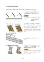
Fastening the module to the module joint
Position the following module on the base foot or
module support. Determine the gap between the
modules (12 mm) by inserting the flat roof mid
clamp. Insert the module fasteners so that the
drilling screw is positioned in the bore hole on the
base foot or module support.
Tightening torque max. 6 Nm.
The screw must not be overtightened!
Clamp on the short frame side.
Connection rail
To reduce ballast on the southern (east-west) edge
or at breaks in the system (e.g. along light strips or
maintenance pathways), position the base trough
150-30 perpendicularly on the base trough as a
connection rail and secure with two screws on each
side. Extend using base trough connectors or
expansion joints at system breaks. Arrange the
expansion joints identically to the expansion joints
of the module supports. Cut the base troughs to
length if required.
The connection rail can be used to install the string
cable or to insert the required ballast. IV 7 applies if
installing without connection rail.
Further rails can be used to redistribute load:
- C-rail 47, 71 and 95, base profile 6.12 m
Please contact us.
Ballast
Place ballast in accordance with the ballast
planning into the base troughs after installing the
modules. The required ballast depends on the
system area and is specified in kg in the ballast
plan.
The use of ballast trays is recommended if using
a lot of ballast (IV 8).
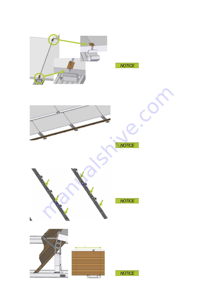
Installing the wind deflector
Guide the wind deflector over the round part of the
module supports and place on the base trough.
Install the adjacent wind deflector for the following
module with an overlap of at least 150 mm to the
first wind deflector.
Secure the wind deflectors to the base troughs with
two screws for each rail and to the round part of the
module support with one or two screws, depending
on the load to be borne (specifications in detail
plan).
The screw must not be overtightened!
> 150
5kg
10kg
23kg
5kg
10kg
23kg


