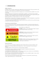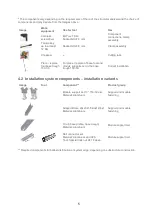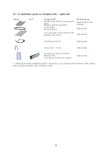
3
novotegra is tested and certified by TÜV Rheinland:
2 INSTALLATION SYSTEM MAINTENANCE
The installation system must be checked annually for stability and proper functioning.
In addition to visually inspecting the components and the roof sealing for damage, all screw and click
connections must also be checked.
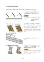
Components can be removed by following the work steps detailed below in the reverse order.
Maintenance work must be carried out by a specialist company with verifiable experience of electrical
systems and working with installation systems.
3 NOVOTEGRA FOR FLAT ROOFS II
The contents of this installation manual describe the installation of the substructure on roofs with sheet or
bitumen waterproofing.
Depending on the roof seal material, separation and/or protection membranes may need to be added
between the roof seal and the substructure. This must be agreed upon directly between the company
installing the PV system, the building owner and the specialist roof sealing company.
The substructure is installed without penetrating the roof. The PV system is secured against wind suction
by providing ballast (e.g. suitable stones), based on the results of the wind tunnel tests for the system. The
required ballast is determined by BayWa r.e. Solar Energy Systems GmbH based on the project data
provided by the installation company. The ballast applies to the planned system; on-site deviations from
planning may lead to different results.
Protection against system sliding is verified based on a coefficient of friction of
µ
= 0.5. This value must be
checked by the installation company prior to installation. If the coefficient of friction is determined by the
installation company in advance, protection can be verified during planning using the determined value.
The system must be secured on site to prevent it from "creeping" due to expansion caused by temperature.
This can be achieved by installing suitable stop points on the roof surface or by anchoring to the parapet,
for example. The connection points on the building and building parts must be able to bear the forces
exerted.
General conditions to be observed in accordance with the wind tunnel test results:
-
Roof incline 0 – 5 degrees
-
Flat roofs with and without parapet
-
Distance from system to roof edge (without parapet) = 0.50 m
-
Distance from system to parapet (inside edge) = 0.50 m
-
Module width = approx. 1.00 m
-
Angle of installation (fixed) = 13°
-
Distance between rows = 1.30 – 2.40 m (closed II) respectively 2.15 – 2.45 m (East-West II)
(distance between the front of a panel and the front of the one behind)
The installation system is designed for loads of up to 2.4 kN/m² (2,400 Pa). The modules are clamped on
the short frame side or, alternatively, on the long frame side in the corners (clamp surface 11 x 52 mm).
This requires approval from the module manufacturer for clamping on the short frame side or on the corner
of the long frame side. Any drainage openings on the module frame may not be blocked. This also applies
to the features provided for this purpose on the support components.


