background image


5

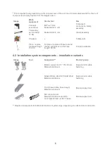
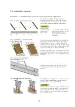
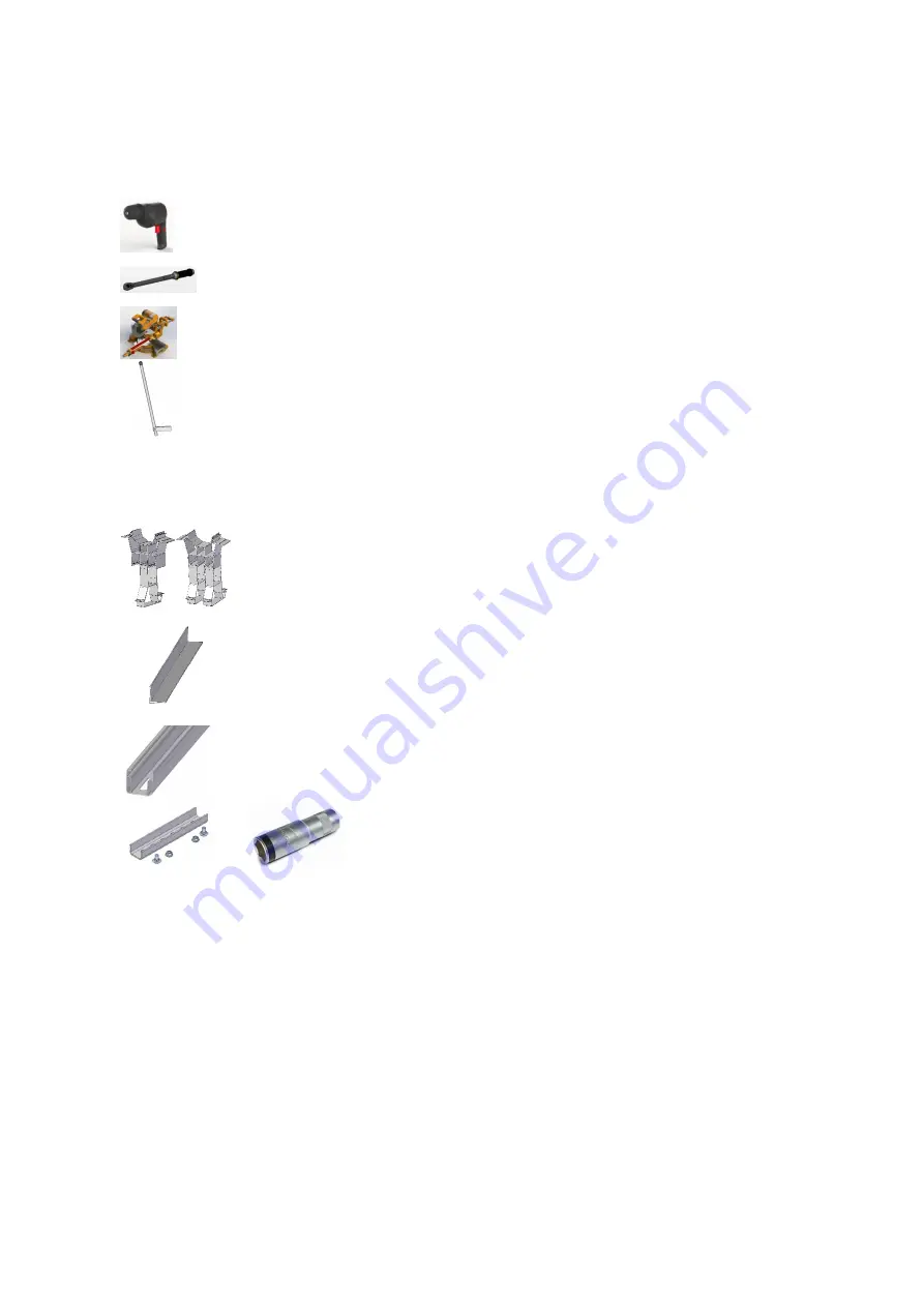
* The components vary depending on the requirements of the roof, the structural analysis and the choice of 
components and may deviate from the images above. 
 

Image 

Work 
equipment 

Use for tool 

Use 


Cordless 
screwdriver 

Bit Torx TX 40 
Socket bit AF 8 mm 

Component 
connections, clamp 
assembly 


Torque key  
up to at least 
12 Nm 

Socket bit AF 8 mm 

Clamp assembly 


Chopsaw 

--- 

Cutting rails 


Place / replace 
tool base trough 
150-30


For place / replace of base foot and 
module supports set in the base 
trough 150-30


Correct installation 


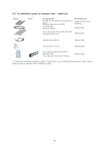
4.2  Installation system components – installation variants 

Image 

Tool 

Component** 

Product group 


Module support set 13° 150-30 e/w 
Material: Aluminium 

Support and module 
fastening 


Support Brace 20x20x1,5 East West 
Material: Aluminium 

Support and module 
fastening 


C-rail (base profile, base trough) 
Material: Aluminium 

Module support rail 


Rail connector set 
Material: Aluminium and V2A 
Tool: Special lock nut AF 18 deep  

Module support rail 


** Required components for ballast distribution at system edge, depending on substructure construction. 


Summary of Contents for closed II

Page 1: ...I Installation manual novotegra for flat roofs closed II East West II...

Page 2: ...uired for installation 4 4 2 Installation system components installation variants 5 4 3 Installation system components optional 6 5 INSTALLING THE SUBSTRUCTURE 7 5 1 Installing the base rails and supp...

Page 3: ...hat the safety information is not observed Warning symbol with signal word Hazard class as per ANSI Z 535 DANGER indicates an immediate hazard Failure to prevent this could result in death or severe i...

Page 4: ...e installation system in accordance with this installation manual is 0 to 5 degrees The given torque values must be observed and tested on a random basis on site Information on structural analysis The...

Page 5: ...may lead to different results Protection against system sliding is verified based on a coefficient of friction of 0 5 This value must be checked by the installation company prior to installation If th...

Page 6: ...ening Flat roof mid clamp Material Aluminium and V2A Tool Socket bit AF 8 mm Support and module fastening Flat roof end clamp Material Aluminium and V2A Tool Socket bit AF 8 mm Support and module fast...

Page 7: ...ce replace of base foot and module supports set in the base trough 150 30 Correct installation 4 2 Installation system components installation variants Image Tool Component Product group Module suppor...

Page 8: ...Plastic Optional item Top cover base trough 150 30 3 00m Material Aluminium Optional item Self locking cable tie Optional item Cable clip d 10 mm Optional item Grounding connector set AF 18 Material V...

Page 9: ...s tightly together push the connectors under the ridge on the base troughs and screw together with two screws on each side Maximum uninterrupted rail length approx 17 m 10 rows with approx 1 70 m gap...

Page 10: ...fter approx 17 m 10 modules next to each other After approx 34 m 20 modules the system must be properly separated The distance between the adjacent base troughs must be 50 mm 5 2 Module installation l...

Page 11: ...f required The connection rail can be used to install the string cable or to insert the required ballast IV 7 applies if installing without connection rail Further rails can be used to redistribute lo...

Page 12: ...Screw the expansion joints to the base troughs On the moving side the two screws must be screwed into the base trough so that they are centred in the slots Installation expansion joint not below a mo...

Page 13: ...es when installing them Install the string cable first IV 6 Fastening the module to the system edge expansion joint Place the drilling screw from the flat roof end clamp centred over the screw channel...

Page 14: ...IV 8 Ballast troughs Using ballast troughs allows small or large size ballst to be securely inserted if required The ballast troughs must be mounted on the side of the base troughs 10kg 35kg 10kg 35k...

Page 15: ...used in the calculation for verification of the anti slide protection for PV systems on flat roofs Coefficients of friction calculated on site can be taken into account and must be provided to BayWa...

Page 16: ...en D 90419 N rnberg Phone 49 7071 98987 300 Phone 49 89 386670 0 Phone 49 911 216646 0 Fax 49 7071 98987 139 Fax 49 89 386670 10 Fax 49 911 216646 10 tue solarenergysystems baywa re com mue solarenerg...

Reviews: