BASS BOOST
0
15
dB
30
250
+
-
-
L
R
SPEAKER
LEVEL IN
GAIN
L
R
INPUT
XOVER
FREQ Hz
MIN
MAX
REMOTE
+
30
125
BASS
BOOST
SLAVE IN
10
80
SUBSONIC
FREQ Hz
SLAVE OUT
SOURCE
SLAVE
NORMAL
PHASE
IN
OUT
.4V - 12.2V
FREQ Hz
PWR \
PROT
15
EN
GL
IS
H
R
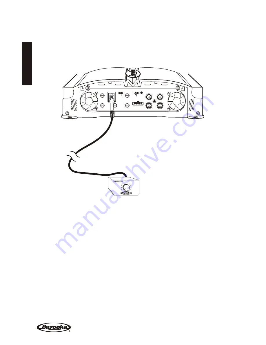
EMOTE BASS CONTROL MODULE
Before connecting the remote, it will be necessary to find a mounting location that will be
easy to access for adjustment. Once you select your mounting location, you will need to
run the control wire from the remote to the amplifier.
To avoid possibility of induced
noise from the car's electrical system (i.e. popping noises or engine noise), run the cable
from the remote to the amplifier away from the car's electrical wiring.
D
IAGNOSTIC LIGHTING
The MGA11000H and MGA11500H are equipped with diagnostic lighting to display the operation
status of the amplifier. The following shows the lighting mode and the description of the
amplifier’s condition.
Top Light On and Blue Power LED On
= Amplifier is running normally.
Top Light On and end Panel Lights are Alternating between Red and Blue
= Amplifier is in thermal protection.
Top Light Blinking Slowly and Red Power light Blinking out of synch with Top Light
= Over Voltage Reduce the
input Voltage.
Top Light Blinking Quickly and Red Panel Light Blinking in Synch with Top Light
= Short Circuit Protection.
Top Light and Red panel Light Blinking Three (3) times with a pause
= Repeated shorts are detected. Remove
short circuit and wait 5 minutes for this error condition to clear. The condition can also be cleared by
removing the main power, for example pulling the fuse.


