- 11 -
6.3 Protection circuit: This unit incorporates the power-saving function. The L/R
channel's protection is performed by cutting off the relay Y401 to cut off the 3
¡À
6
V
p
o
w
e
r
s
u
p
p
ly
w
h
e
n
th
is
u
n
it
is
g
e
ttin
g
s
ta
rte
d
.
C
,
S
R
a
n
d
S
L
c
h
a
n
n
e
ls
p
ro
te
c
tio
n
is
p
e
rfo
rm
e
d
b
y
c
u
ttin
g
o
ff
th
e
re
la
y
Y
4
0
2
to
c
u
t
o
ff
th
e
o
u
tp
u
t
te
rm
in
a
l.
T
h
e
ir
c
o
n
tro
l
te
rm
in
a
ls
a
re
c
o
n
n
e
c
te
d
,
s
o
th
e
re
a
re
n
o
o
u
tp
u
t
fro
m
th
e
fiv
e
c
h
a
n
n
e
ls
w
h
e
n
p
ro
te
c
tin
g
th
is
u
n
it's
s
ta
rt-u
p
.
T
h
is
u
n
it
e
m
p
lo
y
s
fo
u
r
p
ro
te
c
tio
n
fu
n
c
tio
n
s
.
6
.3
.1
S
ta
rt-u
p
D
e
la
y
S
w
itc
h
-o
n
P
ro
te
c
tio
n
C
irc
u
it:
B
e
c
a
u
s
e
th
e
c
irc
u
it
is
n
o
t
s
ta
b
le
w
h
e
n
th
is
u
n
it
is
g
e
ttin
g
s
ta
rte
d
a
n
d
th
e
in
c
u
rre
d
im
p
a
c
t
c
u
rre
n
t
is
v
e
ry
h
a
rm
fu
l
to
th
e
s
p
e
a
k
e
rs
a
n
d
p
o
w
e
r
a
m
p
lific
a
tio
n
c
irc
u
it,
s
o
th
e
d
e
la
y
s
w
itc
h
-o
n
c
irc
u
it
is
p
ro
te
c
te
d
.
W
h
e
n
th
is
u
n
it
is
g
e
ttin
g
s
ta
rte
d
,
+
2
2
V
p
a
s
s
e
s
th
ro
u
g
h
R
4
8
4
to
c
h
a
rg
e
C
4
4
1
.
T
h
e
p
o
s
itiv
e
e
n
d
v
o
lta
g
e
o
f
C
4
4
1
g
e
ttin
g
h
ig
h
e
r
g
ra
d
u
a
lly
.
W
h
e
n
it
s
u
rp
a
s
s
e
s
5
.1
V
,
V
D
4
1
1
is
p
e
n
e
tra
te
d
.
Its
p
o
s
itiv
e
h
ig
h
le
v
e
l
is
a
d
d
e
d
to
th
e
b
a
s
e
o
f
th
e
c
o
m
p
o
u
n
d
tu
b
e
c
o
m
p
ris
in
g
V
4
4
4
&
V
4
4
5
a
n
d
V
4
4
3
&
V
4
4
2
.
T
h
e
s
e
tw
o
c
o
m
p
o
u
n
d
tu
b
e
g
e
t
c
o
n
d
u
c
te
d
a
n
d
th
e
re
la
y
s
Y
4
0
2
a
n
d
Y
4
0
1
a
re
s
w
itc
h
e
d
o
n
,
s
o
th
is
u
n
it
h
a
s
n
o
rm
a
l
o
u
tp
u
t.
T
h
e
s
ta
rt-u
p
d
e
la
y
s
w
itc
h
-o
n
tim
e
d
e
p
e
n
d
s
o
n
th
e
c
o
n
s
ta
n
t
o
f
c
h
a
rg
in
g
a
n
d
d
is
c
h
a
rg
in
g
fro
m
R
4
8
4
to
C
4
4
1
.
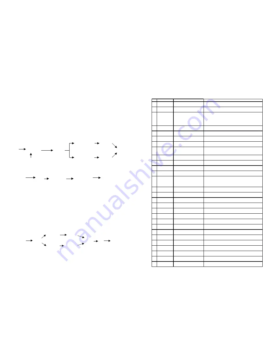
+22V
C
harging
C441
Through R484
Penetrate
VD411
V444
¡¢
V445 conducted
V443
¡¢
V442 conducted
Y402 switched on
Y401 switched on
Normal
output
Defines delay time
6.3.2 Power-saving Control: When press the POWERSAVING button on the front
panel and
Pin 2 of CPU
VD419
V413 conducted
V430 conducted
Relay shut off.
Enter power -saving
mode.
remote control, the pin 2 (E OX) of the CPU sends out a high level. It passes through
VD419 and reaches to the base of V431. When V431 is conducted, V430 is also
conducted. Therefore, the positive end voltage of C441 is decreasing, VD411 is stopped.
The relays Y402 and Y401 are cut off, this unit enters the power-saving mode. At the
same time, the CPU sends out data demands to the front panel display IC and then this
unit enters the power-saving mode.
6.3.3 Mid-point Over-voltage Protection: An over-voltage sampling resistor is
connected to the every channel's output. The channel L's is R478. When there is one
output mid-point DC voltage which is higher than +3.5V or lower than 3.5V, V429 and
V428 are conducted. Their base voltage will decrease and V430 is conducted. At last,
the relay switches off and the protection circuit is getting started.
One
over-voltage
sampling
resistor is
connected to
every
R478
connected
to
L
channel
Above +3.5V
Below +3.5V
V429
conducted
V428 conducted
Collector s
voltage
decreases
V430
conducted
Relay switched
off.
Protection
started up.
- 16 -
2. THE MAIN AMP PART
MAIN PARTS LIST OF THE MAIN AMP BOARD
NO.
DESCRIPTION
SPECIFICATIONS/PART NO.
LOCATION SPECIFICATIONS
1
CARBON-FILM
RESISTOR
1/6W10
¦ ¸
±5% SHAPED 7.5
R417,R418,R422,R423,R444,R445,R449,R450
2
CARBON-FILM
RESISTOR
1/6W100
¦ ¸
±5% SHAPED 7.5
R546~R548,R541
4
CARBON-FILM
RESISTOR
1/6W1K±5% SHAPED 7.5
R506,R507,R510,R511,R514,R515,R518,R519,R522,R523,
R526,R529~R532,R543,R655,R657,R658,R667,R403,
R410,R430,R437,R412,R439,R479,R580,R586,R591,R596,
R601,R606,R611,R616,R619,R622,R626,R570,R575,R686,
R497,R457,R461,R465
5
CARBON-FILM
RESISTOR
1/6W1.5K±5% SHAPED 7.5
R577
6
CARBON-FILM
RESISTOR
1/6W2.2K±5% SHAPED 7.5
R625,R578,R689,R493,R498
7
CARBON-FILM
RESISTOR
1/6W4.7K±5% SHAPED 7.5
R544,R628,R499,R690,R685,R691,R428,R576,R587,R607,
R602,R612,R617,R592,R597,R480,R483,R453,R454,R455
8
CARBON-FILM
RESISTOR
1/6W5.6K±5% SHAPED 7.5
R584,R589,R594,R599,R604,R609,R614,R627
9
CARBON-FILM
RESISTOR
1/6W10K±5% SHAPED 7.5
R581,R583,R588,R593,R598,R603,R608,R613,R620,R623,
R624,R579,R629,R540,R554,R557,R560,R563,R487,R481,
R485,R553,R556,R401,R426,R429,R568,R641
10
CARBON-FILM
RESISTOR
1/6W20K±5% SHAPED 7.5
R661
11
CARBON-FILM
RESISTOR
1/6W22K±5% SHAPED 7.5
R500
12
CARBON-FILM
RESISTOR
1/6W27K±5% SHAPED 7.5
R574,R458,R462,R466
13
CARBON-FILM
RESISTOR
1/6W33K±5% SHAPED 7.5
R446,R419
14
CARBON-FILM
RESISTOR
1/6W47K±5% SHAPED 7.5
R502,R527,R528,R550,R551,R552,R555,R558,R660,
R404,R431,R504,R505,R508,R509,R512,R513,R516,R517,
R520,R521,R524,R525,R682~R684,R536,R537,R663,R664,
R665,R666,R567
15
CARBON-FILM
RESISTOR
1/6W100K±5% SHAPED 7.5
R635,R636,R637,R638,R662,R618,R565,R566,R494~R496,R542
CARBON-FILM
RESISTOR
1/6W1M
¦ ¸
±5% SHAPED 7.5
R534
16
CARBON-FILM
RESISTOR
1/4W47
¦ ¸
±5% SHAPED 10
R535,R545
17
CARBON-FILM
RESISTOR
1/4W100
¦ ¸
±5% SHAPED 10
R420,R421,R447,R448
18
CARBON-FILM
RESISTOR
1/4W4.7K±5% SHAPED 10
R414,R441,R486,R680
19
CARBON-FILM
RESISTOR
1/4W33K±5% SHAPED 10
R411,R438
20
CARBON-FILM
RESISTOR
1/4W47K±5% SHAPED 10
R478,R482
21
CARBON-FILM
RESISTOR
1/4W1M
¦ ¸
±5% SHAPED 10
R533,R675,R678
22
CARBON-FILM
RESISTOR
1/6W18K±5% SHAPED 7.5
R559,R561,R562,R564
23
CARBON-FILM
RESISTOR
1/6W75K±5% SHAPED 7.5
R571,R644,R645,R659
24
CARBON-FILM
RESISTOR
1/4W2K±5% SHAPED 10
R415,R442,R688
25
CARBON-FILM
RESISTOR
1/6W150
¦ ¸
±5% SHAPED 7.5
R501,R503,R539
26
CARBON-FILM
RESISTOR
1/2W220
¦ ¸
±5% SHAPED 12.5
R692~R695
CARBON-FILM
RESISTOR
1/6W2.2M
¦ ¸
±5% SHAPED 7.5
R679
27
CARBON-FILM
RESISTOR
1/6W2.7K±5% SHAPED 7.5
R472,R476,R405,R406,R432,R433,R470,R471,R474,R475
COMPONENTS LIST FO THE MAIN AMPLIFICATION BOARD


