SiI
164
PanelLink
Transmitter
Data Sheet
Data Capture Logic
Video data is input to the
SiI 164
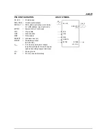
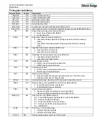
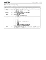
by way of a 12-bit or 24-bit interface. The functionality of this interface is affected
by several of the configuration register settings, as follows.
•
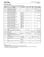
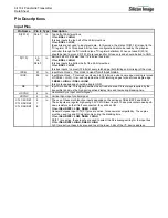
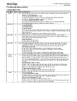
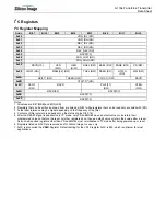
BSEL selects between 12-bit and 24-bit input bus widths.
•
DSEL selects between single-edge and dual-edge modes for the input clocks.
•
EDGE selects between rising and falling edge on the input clocks.
•
CLK+ and CLK- provide the one or two clocks required for latching the input data bus.
•
The PD# input selects the chip power down mode and allows for disabling of the TMDS outputs.
The ISEL/RST# input resets the HDCP engine and internal registers and is asserted after power up and receipt of
a stable input pixel clock.
Summary of Contents for DV985S
Page 1: ...SERVICE MANUAL DV985S...
Page 6: ...5 1 Optical pickup Unit Explosed View and Part List Pic 1...
Page 12: ......
Page 47: ......
Page 49: ......
Page 51: ......
Page 53: ......
Page 55: ......
Page 61: ......

