SiI
164
PanelLink
Transmitter
Data Sheet
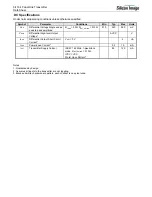
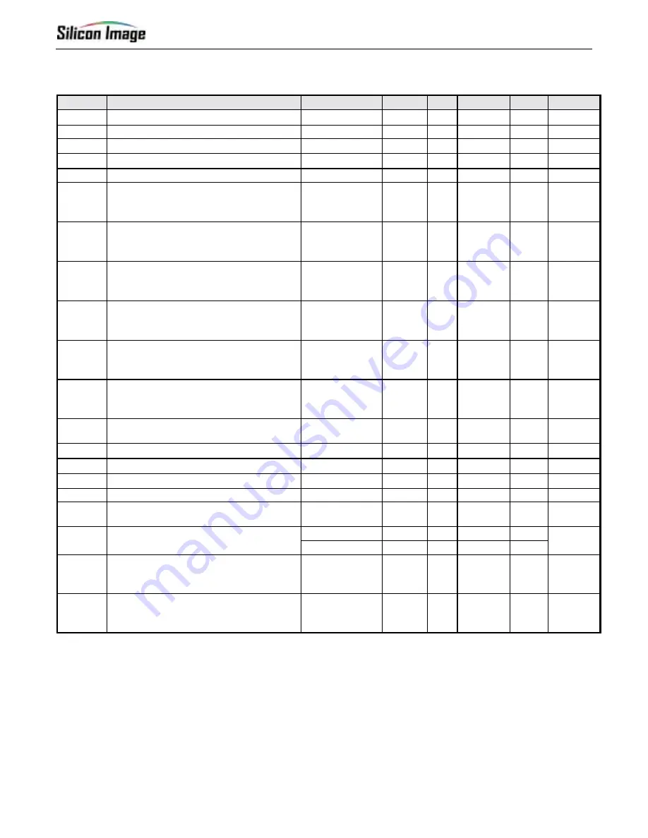
AC Specifications
Under normal operating conditions unless otherwise specified.
Symbol
Parameter
Conditions
Min
Typ
Max
Units
Figure
T
CIP
IDCK Period, 1-pixel/clock
6
40
ns
Figure 3
F
CIP
IDCK Frequency, 1-pixel/clock
25
165
MHz
T
CIH
IDCK High Time at 165MHz
2.0
ns
Figure 3
T
CIL
IDCK Low Time at 165MHz
2.0
ns
Figure 3
T
IJIT
Worst Case IDCK Clock Jitter
2,3
2 ns
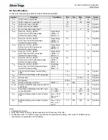
T
SIDF
Data, DE, VSYNC, HSYNC
Setup Time to IDCK falling edge
(Default De-skew Setting)
Single Edge
(DSEL = 0,
EDGE = 0)
1.0 ns
Figure 6
T
HIDF
Data, DE, VSYNC, HSYNC
Hold Time from IDCK falling edge
(Default De-skew Setting)
Single Edge
(DSEL = 0,
EDGE = 0)
0.9 ns
Figure 6
T
SIDR
Data, DE, VSYNC, HSYNC
Setup Time to IDCK rising edge
1
(Default De-skew Setting)
Single Edge
(DSEL = 0,
EDGE = 1)
1.0 ns
Figure 6
T
HIDR
Data, DE, VSYNC, HSYNC
Hold Time from IDCK rising edge
1
(Default De-skew Setting)
Single Edge
(DSEL = 0,
EDGE = 1)
0.9 ns
Figure 6
T
SID
Data, DE, VSYNC, HSYNC
Setup Time to IDCK falling/rising edge
1
(Default De-skew Setting)
Dual Edge
(DSEL = 1,
BSEL = 0)
0.6 ns
T
HID
Data, DE, VSYNC, HSYNC
Hold Time from IDCK falling/rising edge
1
(Default De-skew Setting)
Dual Edge
(DSEL = 1,
BSEL = 0)
1.3 ns
T
DDF
VSYNC, HSYNC Delay from DE falling
edge
1
1T
CIP
ns
Figure 7
T
DDR
VSYNC, HSYNC Delay to DE rising edge
1
1T
CIP
ns
Figure 7
T
HDE
DE high time
1
8191T
CIP
ns
Figure 8
T
LDE
DE low time
1
128T
CIP
ns
Figure 8
T
STEP
De-skew step size increment
DKEN = 1
260
ps
T
RESET
Duration of RESET signal Low required for
valid Reset
10
µs
Figure 5
C
L
= 10pf
700
ns
T
I2CDVD
SDA Data Valid Delay from SCL high
to low transition
3
C
L
= 400pf
2000
ns
Figure 9
S
HLT
Differential Swing High-to-Low Transition
Time
R
LOAD
= 50
Ω
,
R
EXT_SWING
=
510
Ω
170 200 230
ps
Figure 4
S
LHT
Differential Swing Low-to-High Transition
Time
R
LOAD
= 50
Ω
,
R
EXT_SWING
=
510
Ω
170 200 230
ps
Figure 4
Notes
1. Guaranteed by design.
2. Actual jitter tolerance may be higher depending on the frequency of the jitter.
3. All Standard mode I
2
C (100kHz) timing requirements are guaranteed by design. Fast mode I
2
C (400kHz) timing
requirements are guaranteed at 10pf loading.
Summary of Contents for DV985S
Page 1: ...SERVICE MANUAL DV985S...
Page 6: ...5 1 Optical pickup Unit Explosed View and Part List Pic 1...
Page 12: ......
Page 47: ......
Page 49: ......
Page 51: ......
Page 53: ......
Page 55: ......
Page 61: ......

