SiI
164
PanelLink
Transmitter
Data Sheet
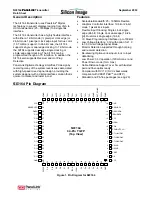
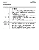
Pin Descriptions
Input Pins
Pin Name
Pin # Type Description
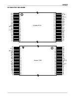
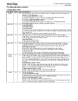
D[23:12]
36-47 In
Top half of 24-bit pixel bus.
When
BSEL = HIGH
,
this bus inputs the top half of the 24-bit pixel bus.
When
BSEL = LOW,
these bits are not used to input pixel data. In this mode, the state of D[23:16] is input to the
I
2
C register CFG. This allows 8-bits of user configuration data to be read by the graphics
controller through the I
2
C interface (see I
2
C register definition). When not used D[23:16]
should be tied to ground. D[15:12] are reserved for
SiI
use only and should be tied to GND.
D[11:0]
50-
55,
58-63
In
Bottom half of 24-bit pixel bus / 12-bit pixel bus input.
When
BSEL = HIGH
,
this bus inputs the bottom half of the 24-bit pixel bus.
When
BSEL = LOW
,
this bus inputs ½ a pixel (12-bits) at every latch edge (both falling and/or rising) of the clock.
IDCK+
57
In
Input Data Clock +.
This clock is used for all input modes.
IDCK- 56
In
Input Data Clock –. This clock is only used in 12-bit mode when dual edge clocking is turned
off (DSEL = LOW). It is used to provide the ODD latching edges for dual clock single edge.
If
BSEL = HIGH
or
DSEL = HIGH
,
this pin is unused and should be tied to GND.
DE 2
In
Input Data Enable. This signal qualifies the active data area. DE is always required by the
transmitter and must be high during active display time and low during blanking time.
HSYNC 4
In
Horizontal Sync input control Signal
VSYNC 5
In
Vertical Sync input control signal.
CTL1/A1/DK1
CTL2/A2/DK2
CTL3/A3/DK3
8
7
6
In
The use of these multi-function inputs depends on the settings of ISEL/RST# and DKEN.
These inputs are regular high-swing 3.3V CMOS level inputs. These pins contain weak pull-
down resistors so that if left unconnected, they will be LOW.
When
ISEL/RST# = LOW, DKEN = LOW
General Purpose Input CTL[3:1] pins are active, for backward compatibility. These pins
must be used to send DC signals only during the blanking time.
When
ISEL/RST# = LOW, DKEN = HIGH
DK[3:1] are active, these inputs are used to select the De-skewing setting for the input bus.
When
ISEL/RST# = HIGH, DKEN = HIGH
A[3:1] are active, these bits are used to set the lower 3 bits of the I
2
C device address.
Summary of Contents for DV985S
Page 1: ...SERVICE MANUAL DV985S...
Page 6: ...5 1 Optical pickup Unit Explosed View and Part List Pic 1...
Page 12: ......
Page 47: ......
Page 49: ......
Page 51: ......
Page 53: ......
Page 55: ......
Page 61: ......

