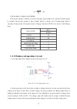
From the above, charge current is 400mA.
When power adapter or USB is connected externally, input voltage is 5V; internal oscillator begins
to oscillate; internal timer begins to time; charger begins to charge and IC automatically fulfills a
complete charge process. During the process of charge, indication of STAT pin is shown in the following
table:
(A)
I
=
REG
1000V
R
PROG
STAT1
MCP73832
Shutdow n
Hi-Z
No Battery Present
Hi-Z
Preconditioning
L
Constant-Current Fast Charge
L
Constant Voltage
L
Charge Complete-Standby
Hi-Z
charge c ycle s tate
3.2.10 Battery voltage detect circuit
1. Low voltage detect circuit diagram is shown in the picture 3.2.10.1:
Figure 3.2.10.1 Low voltage detect circuit
C
3
8
1
0
4
BAT_DET
G
N
D
LRADC1
104
REXT100K
101
LRADC2
103
LRADC0
105
LRADC3
102
R16
100K
1%
R17
100K
1%
BATT
GND
VCC1V8
2
RK2608
2. Working principle: as for the function of battery voltage detect circuit, when we detects that input
voltage of the player is lower than a certain voltage, the player switches off. Battery vltage detect is
fulfilled by Rk2608 and firmware of the player. Pin 105 of Rk2608 is connected with the voltage divide
circuit composed of R16 and R17. The voltage value after battery electric charge is divided through
voltage divide circuit is processed by Rk2608 and then displays on screen to indicate voltage value.
- 25 -


