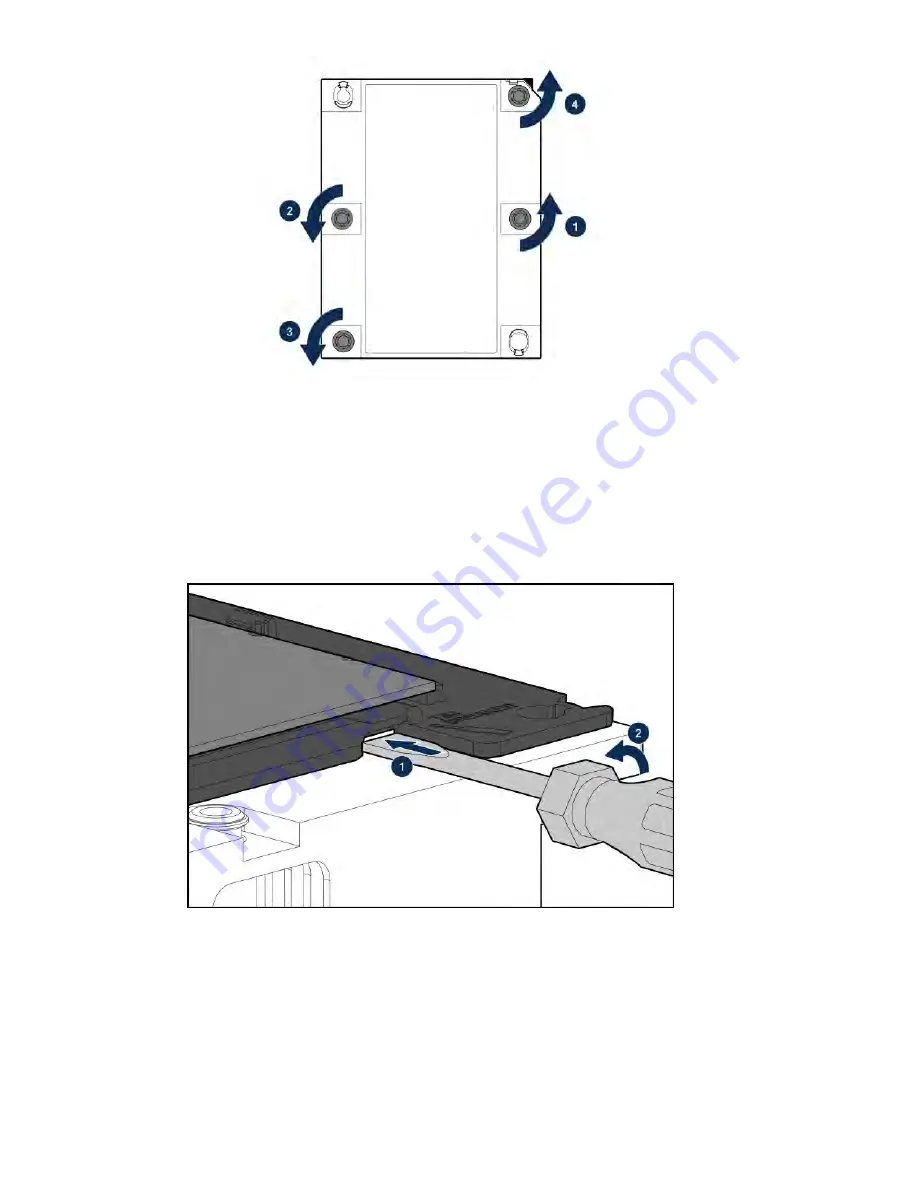
c.
Lift the processor heatsink assembly and move it away from the system board.
d.
Turn the assembly over and place it on a work surface with the processor facing up.
e.
Install the dust cover.
8.
Separate the processor from the heatsink:
a.
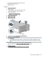
Locate the release slot between the frame and heatsink.
The release slot is across from the Pin 1 indicator and is labeled with a screwdriver.
b.
Insert a 1/4" flathead screwdriver into the release slot.
Be sure that the screwdriver is between the plastic frame and the heatsink.
c.
To lift the processor frame away from the heatsink, slowly rotate the screwdriver.
d.
Unlatch the remaining corners of the frame.
e.
Separate the frame from the heatsink.
9.
Using an alcohol wipe, remove the existing thermal grease.
Allow solvent to dry before making contact with thermal grease.
10.
Align the latches and pin 1 indicator, and then install the frame to the heatsink.
Verify that all of the latches are engaged with the heatsink.
Hardware options installation
109
Summary of Contents for BCD221
Page 7: ...Documentation feedback 157 Contents 7 ...
Page 27: ...Component identification 27 ...
Page 43: ...Operations 43 ...
Page 124: ...Box 2 to SAS Expander All boxes 124 Cabling ...
Page 126: ...Box 2 Box 3 126 Cabling ...


