background image

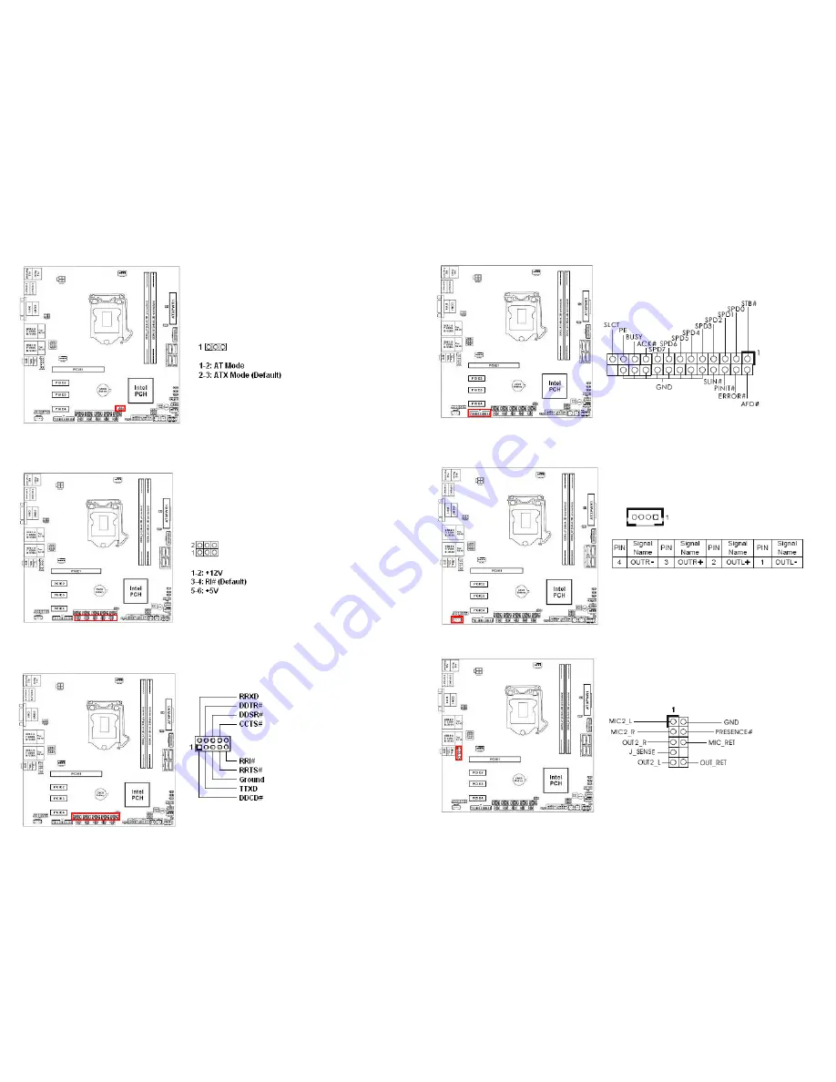
23. ATX/ AT Mode Select: PWR_JP1 


24. COM2/3/4/5/6 Pin#9 Power Setting Jumper:   

      PWR_COM2, PWR_COM3, PWR_COM4, PWR_COM5, PWR_COM6


25. COM2, COM3, COM4, COM5, COM6 Headers (RS232 ONLY):  

      COM2, COM3, COM4, COM5, COM6  


26. LPT Port Header: LPT1 


28. 3W Audio AMP Output: SPEAKER1 (Corresponding Volume Control 

      available at BIOS) 


29. Front Panel Audio Header: HD_AUDIO1 


Summary of Contents for 71172

Page 1: ...a seemingly small incorrect adjustment or modification in the BIOS setup can render your system unstable or unusable The incorrect BIOS setup is not covered by your motherboard s manufacturer warranty Additional Information Additional information on setting this board up can be found in the User s Manual in the provided CD ROM The Online User s Manual and FAQ Knowledge Base can be found on our web...

Page 2: ...ight blue This port connects a tape CD DVD player or other audio sources 7 AUDIO Line out port Green This port connects a headphone or a speaker 8 AUDIO Microphone port Pink This port connects a microphone 9 USB3_45 USB 3 0 Connectors These two Universal Serial Bus USB ports are available for connecting USB 3 0 devices 10 USB2_89 USB 2 0 Connectors These two 4 pin Universal Serial Bus USB ports ar...

Page 3: ...Fan Connector CPU_FAN1 6 Reserved for Factory Use Only PWR_LOSS1 7 24 Pin ATX Power Connector ATXPWR1 8 USB Power Setting Jumper USB3_PWR2 For USB3 0 Port USB3_3_4 9 USB3 0 Header USB3_3_4 10 SATA3 Connectors SATA3_1 SATA3_2 SATA3_3 SATA3_4 ...

Page 4: ...IO Input Output Power Select JGPIO_PWR1 13 GPIO Signals Pull High Pull Low Selection JGPIO_SET1 14 Digital Input Output Header JGPIO1 15 Reserved for Factory Use Only SPI2 16 Chassis Fan Connector 2 CHA_FAN2 ...

Page 5: ...18 System Panel Header PANEL1 19 Chassis Intrusion Headers CI1 CI2 20 USB2 0 Headers USB2_0_1 USB2_2_3 21 Clear CMOS Header CLRMOS1 22 USB Ports Power Setting Jumpers USB2_PWR2 For USB2 0 Port USB2_0_1 USB2_PWR3 For USB2 0 Port USB2_2_3 ...

Page 6: ...g Jumper PWR_COM2 PWR_COM3 PWR_COM4 PWR_COM5 PWR_COM6 25 COM2 COM3 COM4 COM5 COM6 Headers RS232 ONLY COM2 COM3 COM4 COM5 COM6 26 LPT Port Header LPT1 28 3W Audio AMP Output SPEAKER1 Corresponding Volume Control available at BIOS 29 Front Panel Audio Header HD_AUDIO1 ...

Page 7: ... cover during processor installation please save the processor socket cover In the event that the desktop board needs to be returned for service or any time the processor is removed the cover should be replaced on the processor socket Do not Touch Socket Contact ...

Reviews: