ECM-3455J User’s Manual
7
Contents
Chapter 1: System Setup ..............................................................................................
14
1.1
Welcome! ................................................................................................................................ 14
1.2
Packing Contents ................................................................................................................... 14
1.3
Before you proceed ................................................................................................................ 15
1.4
Mainboard Overview............................................................................................................... 16
1.4.1
Mounting Holes ....................................................................................................................... 16
1.4.2
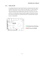
Onboard LEDs ........................................................................................................................ 17
1.4.3
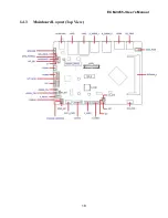
Mainboard Layout (Top View/ Bottom View) .......................................................................... 18
1.4.4
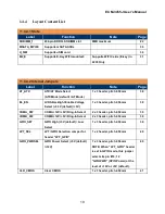
Layout Content List................................................................................................................. 19
1.4.4.1
Slots ........................................................................................................................................ 19
1.4.4.2
Internal Jumpers ..................................................................................................................... 19
1.4.4.3
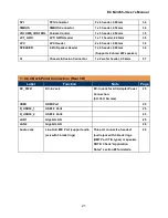
Internal Headers ..................................................................................................................... 20
1.4.4.4
Back Panel Connectors .......................................................................................................... 21
1.5
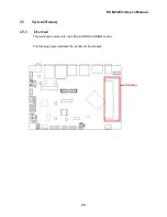
System Memroy ...................................................................................................................... 22
1.5.1
Overview ................................................................................................................................. 22
1.5.2 Memory Configurations .......................................................................................................... 23
1.5.3 Installing the DDR4 SODIMM ................................................................................................. 23
1.5.4
Removing the DDR4 SODIMM
..............................................................................
24
1.6
Back Panel (Rear I/O Ports) ................................................................................................... 25
1.6.1
Back Panel Connectors .......................................................................................................... 25
1.7
Connectors/Headers............................................................................................................... 27
1.7.1
4-Pins Power Connector: DCIN_PWR ................................................................................... 27
1.7.2
Front Panel Connector: F_Panel ............................................................................................ 28
1.7.3
System Fan Connector: SYS_FAN ........................................................................................ 28
1.7.4
Seriall ATA 3.0 Connector: SATA3 ........................................................................................ 29
1.7.5
SATA Power Connector: SATA_PWR ................................................................................. 29
1.7.6
mSATA/ Mini-PCIE Connector: MSATA_MPCIE .................................................................... 30
1.7.7
uSIM Card Slot: U_SIM ........................................................................................................ 30
1.7.8
M.2 Socket: M2_E (E-Key, Supporrts Wifi Cards in 2230 Only) ............................................ 31
1.7.9
Front USB2.0 Headers: F_USB1, F_USB2 ............................................................................ 31
1.7.10
COM Ports: COMA, COMB .................................................................................................... 32
1.7.11
LVDS Panel Connector: LVDS ............................................................................................... 32
1.7.12
LVDS Panel Backlight Connector: BACKLIGHT .................................................................... 33
1.7.13
I2C Header: I2C ...................................................................................................................... 33


