background image

BIOS Setup

This chapter provides information on the BIOS Setup program and 
allows you to con

fi

 gure  the system for optimum use.

You may need to run the Setup program when:


An error message appears on the screen during the sys-
tem booting up, and requests you to run SETUP.


You want to change the default settings for customized 
features.

3

Chapter 3

Summary of Contents for MX525D

Page 1: ...WWW BCMCOM COM User s Manual MX525D DC Industrial Mini ITX Motherboard...

Page 2: ...ed Micro Devices Inc Award is a registered trademark of Phoenix Technologies Ltd Sound Blaster is registered trademark of Creative Technology Ltd Realtek is registered trademark of Realtek Semiconduct...

Page 3: ...on the equipment should be noted Never pour any liquid into the opening that could damage or cause electrical shock If any of the following situations arises get the equipment checked by service pers...

Page 4: ...interference by one or more of the measures listed below Reorient or relocate the receiving antenna Increase the separation between the equipment and receiver Connect the equipment into an outlet on...

Page 5: ...k Altger te nicht mehr als kommunale Abf lle entsorgt werden BCM hat europaweit verschiedene Sammel und Recyclingunternehmen beauftragt die in die Eu rop ische Union in Verkehr gebrachten Produkte am...

Page 6: ...producten die de merknaam BCM dragen en verkocht zijn in de EU Deze goederen kunnen geretourneerd worden op lokale inzamelingspunten SRPSKI Da bi za titili prirodnu sredinu i kao preduze e koje vodi r...

Page 7: ...ch sb rn ch MAGYAR Annak rdek ben hogy k rnyezet nket megv dj k illetve k rnyezetv d k nt fell pve az BCM eml kezteti nt hogy Az Eur pai Uni EU 2005 augusztus 13 n hat lyba l p az elektromos s elek t...

Page 8: ...r 1 Overview 1 1 Mainboard Specifications 1 2 Mainboard Layout 1 4 Chapter 2 Hardware Setup 2 1 Quick Components Guide 2 2 Memory 2 3 Power Supply 2 4 Back Panel I O 2 5 Connector 2 8 Jumper 2 16 Slot...

Page 9: ...the DC Power verion Based on the innovative Intel ICH8M chipset for optimal system efficiency the IM PV C accommodates the Intel Pineview D Dual core D525 processor and supports 2 DDR3 800MHz SO DIMM...

Page 10: ...on Interface 1 x Mini PCI Express 1 x PCI slot 1 x Compact Flash socket Back I O Panel COM Ports 1 x RS 232 422 485 1 x RS 232 VGA 1 x DB 15 DVI 1 x DVI D LAN 2 x RJ 45 USB 4 x USB Audio 1 x 3 jacks A...

Page 11: ...ront Panel Connector Front USB Connector Fan Power Connector LVDS Inverter Connector Mini PCIe Slot GPIO Connector DC Power Connector Optional SATA Power Connector Optional CF Mode Jumper COM Power Se...

Page 12: ...ion on mainboard hardware configurations Incorrect setting of jumpers and connectors may damage your mainboard Please pay special attention not to connect these headers in wrong direction DO NOT adjus...

Page 13: ...nnector p 2 10 USB Connector p 2 11 Fan Power Connector p 2 17 LVDS Inverter Connector p 2 14 Mini PCIe Slot p 2 19 GPIO Connector p 2 12 DC Power Connector Optional p 2 4 SATA Power Connector Optiona...

Page 14: ...nd insert the DIMM into the slot 2 Push the DIMM gently downwards until the slot levers click and lock the DIMM in place 3 To uninstall the DIMM flip the slot levers outwards and the DIMM will be rele...

Page 15: ...V 1 9 G r o u n d 7 G r o u n d 2 2 5 V 1 0 1 2 V 2 0 R e s 8 P W R O K 2 3 5 V 1 1 1 2 V 2 1 5 V 9 5 V S B 2 4 G r o u n d 1 2 3 3 V DC Power Connector JPWR1 DC Version This DC In connector provides...

Page 16: ...NAL DESCRIPTION 1 2 3 4 5 6 7 8 9 DCD RXD TXD DTR GND DSR RTS CTS VCC_COM1 or RING Data Carrier Detect Receive Data Transmit Data Data Terminal Ready Signal Ground Data Set Ready Request To Send Clear...

Page 17: ...Transmit Data Positive No Connection Signal Ground No Connection No Connection No Connection No Connection RS 485 VGA Port The DB15 pin female connector is provided for monitor DVI I Port The DVI I D...

Page 18: ...in No Transmission Yellow Yellow Lighting OFF Transmission Yellow Yellow Blinking OFF 100M Cable Plug in No Transmission Yellow Yellow Lighting Green Green Lighting Transmission Yellow Yellow Blinking...

Page 19: ...cord this status and show a warning message on the screen To clear the warning you must enter the BIOS utility and clear the record 1 C I N T R U 2 G r o u n d Serial ATA Connector SATA1 SATA3 This co...

Page 20: ...e is the positive and should be connected to the 12V the black wire is Ground and should be connected to GND If the mainboard has a System Hardware Monitor chipset onboard you must use a specially des...

Page 21: ...T _ P H 5 M S C L K _ P H 7 G N D 9 N C Front Panel Connector JFP1 This front panel connector is provided for electrical connection to the front panel switches LEDs and is compliant with Intel Front...

Page 22: ...for connecting high speed USB interface peripherals such as USB HDD digital cameras MP3 players printers modems and the like 1 V C C 3 U S B 0 1 0 N C 5 U S B 0 7 G r o u n d 9 N o P i n 8 G r o u n...

Page 23: ...JLPT1 The mainboard provides a 26 pin header for connection to an optional parallel port bracket The parallel port is a standard printer port that sup ports Enhanced Parallel Port EPP and Extended Ca...

Page 24: ...al device to it through an optional serial port bracket 8 C T S 3 T X D 1 D C D 6 D S R 5 G N D 4 D T R 7 R T S 2 R X D 9 V C C _ C O M PIN SIGNAL DESCRIPTION 1 2 3 4 5 6 7 8 9 DCD RXD TXD DTR GND DSR...

Page 25: ...pically used with flat panels After connecting an LVDS interface flat panel to the JLVDS1 be sure to check the panel datasheet and set the JVDD1 jumper to proper power voltage LCD Inverter Connector J...

Page 26: ...llows you to connect the front panel audio and is compliant with Intel Front Panel I O Connectivity Design Guide SPDIF Out Connector JSPDO1 This connector is used to connect S PDIF Sony Philips Digita...

Page 27: ...the CMOS RAM the system can automatically boot OS every time it is turned on If you want to clear the system configuration set the jumper to clear data Important Important You can clear CMOS by short...

Page 28: ...r JCOMP6 This jumper is used to select the pin 9 function of the COM1 port JCOMP6 1 1 5V 12V 1 COM Power Select Jumper JCOMP1 JCOMP5 These jumpers are used to select the pin 9 power voltage of the COM...

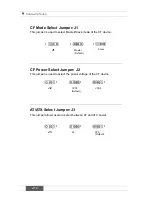
Page 29: ...Slave mode of the CF device J1 1 1 Master Default Slave 1 CF Power Select Jumper J2 This jumper is used to select the power voltage of the CF device J2 1 1 VCC3 Default VCC5 1 AT ATX Select Jumper J3...

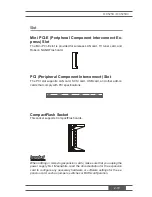
Page 30: ...e sure that you unplug the power supply first Meanwhile read the documentation for the expansion card to configure any necessary hardware or software settings for the ex pansion card such as jumpers s...

Page 31: ...nd allows you to configure the system for optimum use You may need to run the Setup program when An error message appears on the screen during the sys tem booting up and requests you to run SETUP You...

Page 32: ...espond and you still wish to enter Setup restart the system by turning it OFF and On or pressing the RESET button You may also restart the system by simultaneously pressing Ctrl Alt and Delete keys Im...

Page 33: ...r symbol appears to the left of certain fields that means a sub menu can be launched from this field A sub menu contains additional options for a field parameter You can use arrow keys to highlight th...

Page 34: ...ity of boot devices Security Use this menu to set supervisor and user passwords Chipset This menu controls the advanced features of the onboard Northbridge and Southbridge Power Use this menu to speci...

Page 35: ...Type Press PgUp or PgDn to select Manual None or Auto type Note that the specifications of your drive must match with the drive table The hard disk will not work properly if you enter improper inform...

Page 36: ...S M A R T This allows you to activate the S M A R T Self Monitoring Analysis Reporting Technol ogy capability for the hard disks S M A R T is a utility that monitors your disk status to predict hard...

Page 37: ...t the Num Lock status when the system is powered on Setting to On will turn on the Num Lock key when the system is powered on Setting to Off will allow users to use the arrow keys on the numeric keypa...

Page 38: ...of malicious buffer overflow attacks when combined with a supporting operating system This functionality allows the processor to classify areas in memory by where application code can execute and whe...

Page 39: ...on and decreased aver age heat production Intel R C State Tech C state performance indicates the ability to run the processor in lower power states when the PC is idle This setting enables disables th...

Page 40: ...This setting enables disables the initialization of the onboard LAN Boot ROM during bootup Selecting Disabled will speed up the boot process Super IO Configuration Serial Port 1 2 3 4 5 Address Paral...

Page 41: ...iding the overheating to damage your system FAN1 Type This setting specifies the fan type Min Speed This setting specifies the minimum fan speed Smart SYSFAN Target This setting allows users to set a...

Page 42: ...Health Configuration These items display the current status of all monitored hardware devices components such as voltages temperatures and all fans speeds GPIO Configuration GPO 1 2 3 4 Data This sett...

Page 43: ...es This setting determines whether or not to try other boot devices when the preset boot device is not available Removable Drives This setting allows users to set the priority of the removable devices...

Page 44: ...oot These settings allow you to set or change the user password Boot Sector Virus Protection This function protects the BIOS from accidental corruption by unauthorized users or computer viruses Chassi...

Page 45: ...ned by the Trusted Computing Group TCG TPMs are special purpose inte grated circuits ICs built into a variety of platforms to enable strong user authentication and machine attestation essential to pre...

Page 46: ...ormance Setting it to DVMT Mode ensures that system memory is dynamically allocated for optimal balance between graphics and system performance DVMT FIXED Memory When set to DVMT FIXED Mode the graphi...

Page 47: ...ating system supports ACPI you can choose to enter the Standby mode in S1 POS or S3 STR fashion through the setting of this field Restore on AC Power Loss This setting specifies whether your system wi...

Page 48: ...of onboard LAN mini PCI E is de tected Resume On PME When setting to Enabled this setting allows your system to be awakened from the power saving modes through any event on PME Power Manage ment Even...

Page 49: ...Setup Utility Discard Changes Abandon all changes and continue with the Setup Utility Load Optimal Defaults Use this menu to load the default values set by the mainboard manufacturer specifically for...

Page 50: ...Chapter 4 System Resources This chapter provides information on system resources 4...

Page 51: ...hipset initialization Re enable CACHE Verify that flat mode is enabled D4 Test base 512KB memory Adjust policies and cache first 8MB Set stack D5 Bootblock code is copied from ROM to lower system memo...

Page 52: ...Initializes data variables that are based on CMOS setup questions Initializes both the 8259 compatible PICs in the system 05 Initializes the interrupt controlling hardware generally PIC and inter rupt...

Page 53: ...mation 38 Initializes different devices through DIM See DIM Code Checkpoints section of document for more information 39 Initializes DMAC 1 DMAC 2 3A Initialize RTC date time 3B Test for total memory...

Page 54: ...modules Fill the free area in F000h segment with 0FFh Initializes the Microsoft IRQ Routing Table Prepares the runtime lan guage module Disables the system configuration display if needed A4 Initiali...

Page 55: ...System Resources 4 6 Resource List ICH8M GPIO...

Page 56: ...MX525D MX525DC 4 7 SIO GPIO...

Page 57: ...IO pin connection design with 4 input and 4 output pins GPI is design for input GPO is design for output Example 1 Read data from GPIO Pin3 GPI00 the Pin3 GPI00 status value is at address F2 bit 0 Ste...

Page 58: ...x Step 4 Get data from port 0x4f Save current state Byte tmp Inp 0x4f Read current data for adding the output in bit4 Step 5 Write data to port 0x4f only set bit 4 to high and write back Out 0x4f tmp...

Page 59: ...urces 4 10 Step 4 Get data from port 0x4f Save current state Byte tmp Inp 0x4f Read current data for adding the output in bit4 Step 5 Write data to port 0x4f only set bit 4 to low and write back Out 0...

Reviews: