background image

Pg. 4

2

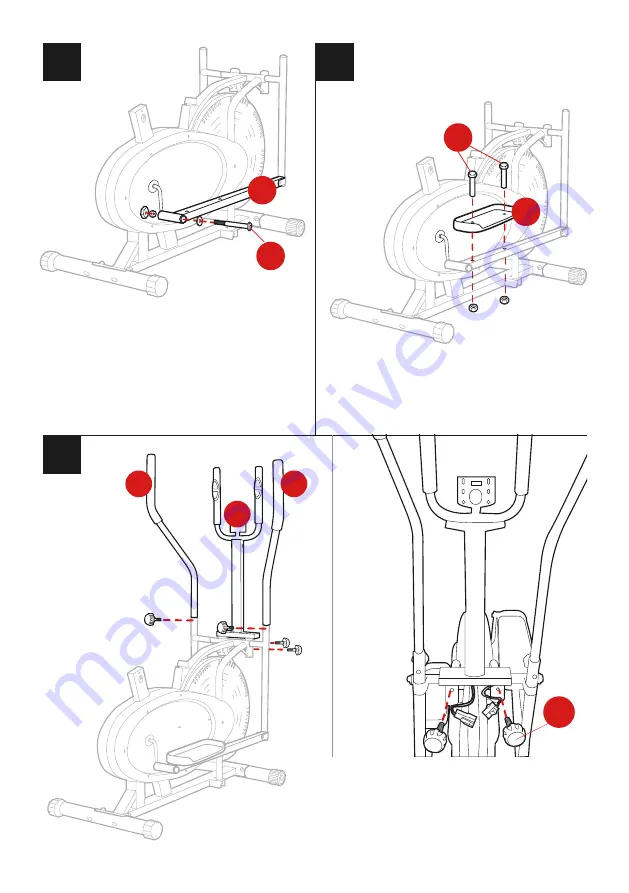
Remove hardware from part 4 pedal hinge bolt 

(right) and insert it through part F right pedal 

tubing, replacing the hardware in the appropriate 

places as shown. Repeat this process on the left 

side with part 3 and part G.
NOTE: The left pedal hinge bolt must be screwed 

counter-clockwise, and the right must be screwed 

clockwise. If the hinge does not screw easily, adjust 

the angle of the bolt.

4

F

1

I

FRONT VIEW

6

Unscrew the knobs on the coupler bars, install the 

parts J and K left/right handle bars, then replace 

the knobs to secure the handlebars.
Install the part L middle handle bar with two part 

6 knobs. Join the appropriate wires at the bottom 

of the assembly.

4

J

K

L

3

Install part H and I pedals with four part 1 nut and 

bolt sets, two on each pedal. 

Summary of Contents for SKY1733

Page 1: ...SKY1733 Ver 2 INSTRUCTION MANUAL Elliptical Bike ...

Page 2: ... PCS 9 4 PCS 10 2 PCS A 1 PC B 1 PC C 1 PC D 1 PC E 1 PC BELLOW FRONT BOTTOM TUBE REAR BOTTOM TUBE RIGHT COUPLER BAR LEFT COUPLER BAR F 1 PC G 1 PC I 1 PC J 1 PC K 1 PC RIGHT PEDAL TUBING L 1 PC M 1 PC N 1 PC MIDDLE HANDLE BAR MONITOR SEAT LEFT PEDAL TUBING RIGHT PEDAL LEFT HANDLE BAR RIGHT HANDLE BAR H 1 PC LEFT PEDAL O 1 PC SEAT TUBE 1 PC L R M10X45 M10X57 φ15 6X88 8X1 2 S13 S16 S18 φ15 6X88 8X1...

Page 3: ...nt bottom tube has wheels to easily maneuver your elliptical Remove the hardware from the part 5 handle bar shaft to insert it through the part D right coupler bar main frame and part E left coupler bar Replace the hardware in the appropriate places as shown NOTE Use two Allen wrenches to tighten both ends of the handle bar shaft at the same time Tighten one side clockwise and the other side count...

Page 4: ...r clockwise and the right must be screwed clockwise If the hinge does not screw easily adjust the angle of the bolt 4 F 1 I FRONT VIEW 6 Unscrew the knobs on the coupler bars install the parts J and K left right handle bars then replace the knobs to secure the handlebars Install the part L middle handle bar with two part 6 knobs Join the appropriate wires at the bottom of the assembly 4 J K L 3 In...

Page 5: ... to attach the seat to the part O seat tube Then slide the part A bellow onto the seat tube and slide the assembled seat onto the main frame Use a part 7 tri knob to secure it in place Install part 8 9 and 10 nut caps in the appropriate locations 8 9 10 N O A 5 7 10 8 ...

Page 6: ...t or excessive exercise can damage your health Stop your workout and consult with your doctor immediately if you experience any of the following Dizziness Nausea Chest pain Back pain Any other health related symptoms Do not use any exercise equipment if it is not assembled properly Be sure to inspect your machine periodically to ensure all nuts and bolts are securely tightened and that your machin...

Page 7: ...n the display This displays the total distance of your workout from start to finish Press and hold SET to set an exercise distance goal When the set reaches your goal the alarm will sound for 5 seconds CALORIES Press the MODE button until CAL appears on the display This displays the total calories burned during your workout from start to finish Press and hold SET to set a calories burned goal When...

Page 8: ... are not considered undamaged until they are received by Best Choice Products and verified as such All damages to items are the customer s responsibility until the item has been received by and acknowledge by Best Choice Products as undamaged CONTACT US WE RE HERE 7 DAYS A WEEK TO HELP YOU WARNING Manufacturer and seller expressly disclaim any and all liability for personal injury property damage ...

Reviews: