38
6. ISTRUZIONI D’USO (BF)_P4 11-16 rev. 0
6.4
6.5
IT
IT
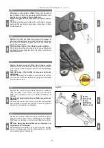
6.4 Regolazione lama
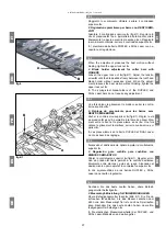
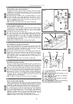
Per la barra LASER allentare il premilama
C
(fig.6/2); avvi-
cinare la lama
D
ai blocchetti di usura
E
agendo sul premi-
lama e serrare le viti lasciando un piccolo gioco di 0,1 mm.
Per la barra con i DENTI SEMIFITTI allentare le viti
H
dei
premilama
F
(fig.6/3) e con un cacciavite avvicinare la stri-
scia di consumo
L
alla striscialama
G
, lasciando tra loro un
gioco di 0.1 / 0.5 mm. Serrare quindi nuovamente le viti
H
dei premilama.
Le barre DUPLEX e DUAL Laser non richiedono regola-
zione lama.
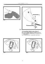
6.5 Sostituzione lama
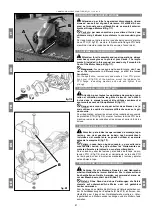
Tutti i tipi di lama si sostituiscono allentando le viti
A
e to-
gliendo l'attacco lama
B
(fig.6/4).
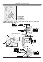
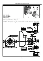
Se necessario, allentare i premilama (fig.6/5 e 6/6) e sfila-
re la lama (fig.6/7 e 6/8).
PER LA REGOLAZIONE, VEDI PARAGRAFO PRECE-
DENTE.
Nel rimontare la lama occorre prestare attenzione a rimon-
tare correttamente l’attacco lama
B
, poi serrare forte le
due viti
A
. Regolare l’attacco lama
B
come da fig.6/11.
6.4
6.5
EN
EN
6.5 Blade replacement
All types of blades are replaced loosing the bolts
A
and
removing the blade holder
B
(fig.6/4).
If necessary loosen the blade holder (fig.6/5 and 6/6) and
remove the blade (fig.6/7 and 6/8).
FOR THE ADJUSTMENT SEE PREVIOUS PARA-
GRAPH.
In re-assembling the blade, pay careful attention to cor-
rectly re-assembling the blade attachment B, then securely
tighten the two screws A. Adjust the blade attachment B as
shown in the figure 6/11.
6.4 Blade adjustment
To adjust the LASER bar loosen the blade-holder
C
(fig.
6/2); approach blade to the wear blocks
E
operating on the
blade holder and tighten the bolts allowing a small slack of
0,1 mm.
For the bar with FINGERS, loosen the screws
H
on the
blade-clamping devices
F
(fig.6/3), and using a screwdri-
ver draw the blade guide
L
closer to the blade bar
G
, lea-
ving a space of 0.1 / 0.5 mm between them. Then tighten
the screws
H
on the blade-clamping devices once again.
The DUPLEX and DUAL Laser bars does not require blade
adjustments.
6.4
6.5
FR
FR
6.4 Réglage de la lame
Pour la barre LASER lâcher le presse lame
C
(fig.6/2);
approcher la lame
D
aux blocs d’usure
E
et serrer les vis
en laissant un petit jeu de 0,1 mm.
Pour la barre avec DENTS SEMI-SERRÉS, il faut dévisser
les vis
H
des appuie-lames
F
(fig.6/3) et avec un tournevis,
il faut rapprocher la bande guide
L
à la lame coupante
G
,
en laissant entre elles un jeu de 0,1 / 0,5 mm. Il faut ensuit-
e serrer de nouveau les vis
H
des appuie-lames.
Les barres DUPLEX et DUAL Laser n’ont pas besoin de
réglage de la lame.
6.5 Replacement de la lame
Tous les types de lames doivent être remplacé comme
suit: lâcher les vis
A
et ôter l’attache de la lame
B
(fig.6/4).
Si nécessaire lâcher le presse-lame (fig.6/5 et 6/6) aussi et
désenfiler la lame (fig.6/7 et 6/8).
POUR LE REGLAGE VOIR LE PARAGRAPH PRÉCE-
DENT.
En remontant la lame, il faut faire attention à remonter cor-
rectement le branchement de la lame B, puis serrer bien
fort les deux vis A. Régler le branchement de la lame B
comme sur la figure 6/11.
6.4
6.5
ES
ES
6.4 Regulación de la cuchilla
Para regular la barra LASER aflojar la guia cuchilla
C
(fig.
6/2); aproximar la cuchilla
D
a los bloquetos de desgaste
E
y apretar los tornillos dejando un pequeño juego de 0,1 mm.
Para la barra con DIENTES SEMIJUNTOS aflojar los tor-
nillos
H
del sujetacuchilla
F
(fig.6/3) y con un destornillador
acercar la guía
L
al perfil de fijación de los dientes
G
, de-
jando entre ambos un juego de 0.1 / 0.5 mm. A continua-
ción apretar nuevamente los tornillos
H
del sujetacuchilla.
Las barras DUPLEX y DUAL Laser no necesitan regular la
cuchilla.
6.5 Sustitución de la cuchilla
Todos los tipos de cuchilla se sustituyen asi: aflojar los
tornillos
A
y sacar el ataque cuchilla
B
(fig.6/4).
Si necesario aflojar también la guia cuchilla (fig.6/5 y 6/6)
entonces sacar la cuchilla (fig.6/7 y 6/8).
PARA LA REGULACION VEER PARAGRAFO PRÉCE-
DENTE.
Al volver a montar la cuchilla, hay que prestar atención y
colocar correctamente el acople de la cuchilla B. A conti-
nuación, apretar fuerte los dos tornillos A. Hay que regular
el acople de la cuchilla B tal y como se indica en la figura
6/11.
6.4
6.5
DE
DE
6.4 Messereinstellung
Für den LASER Mähbalken lösen Sie den Messerhalter
C
(Bild 6/2); nähern Sie das Messer
D
den Verschleißstü-
cken
E
bei dem Messerehalter und verschrauben Sie wie-
der die Schrauben und ein spiel lassen von 0,1 mm.
Für die FINGERMÄHBALKEN die Schrauben
H
des Mes-
serblocks
F
(Bild 6/3) lösen und die Messerführung
L
mit
einem Schraubenzieher dem Messerhalter
G
bis auf 0,1 /
0,5 mm nähern.
Bei dem DUPLEX- und DUAL Laser-Mähbalken ist keine
Messereinstellung erforderlich.
6.5 Messerersatz
Alle Messer werden wie folgt ersetzt: Schrauben
A
lösen
und Messerkopf
B
beseitigen (Bild 6/4).
Wenn nötig Sie auch die Messerhalter (Bild 6/5 und 6/6)
und ziehen Sie das Messer heraus (Bild 6/7 und 6/8).
FÜR DIE EINSTELLUNG SIEHE VORHERIGE AB-
SCHNITT.
Beim Wiedereinbau des Messers ist darauf zu achten,
dass der Messeranschluss B ordnungsgemäß eingesetzt
wird; die beiden Schrauben A feste anziehen. Den An-
schluss B entsprechend Abbildung 6/11 justieren.

