background image

BDDF00171 Issue 4

37/39

BD Alaris™ MRI Capsule

Electromagnetic Emissions

Guidance and Manufacturer’s Declaration 

– Electromagnetic Immunity – Life Support Equipment

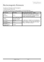
The MRI Capsule is intended for use in the electromagnetic environment specified below .

The customer or the user of the MRI Capsule should ensure that it is used in such an environment .

Immunity Test

EN 60601-1-2

Test Level

Compliance Level Electromagnetic Environment – Guidance

EN 61000-4-6

Conducted 

disturbances 

induced by RF 

fields

EN 61000-4-3

Radiated RF EM 

fields

3 V 

0 .15 MHz – 

80 MHz

6 V  in ISM bands 

between

0 .15 MHz and 

80 MHz

80 % AM at 1 kHz

3 V/m

80 MHz – 2 .7 GHz

80 % AM at 1 kHz

3 V 

0 .15 MHz – 

80 MHz

6 V  in ISM bands 

between

0 .15 MHz and 

80 MHz

80 % AM at 1 kHz

3 V/m

80 MHz – 2 .7 GHz

80 % AM at 1 kHz

Portable and mobile RF communications equipment 

should be used no closer to any part of the MRI Capsule, 

including cables, than the recommended separation 

distance calculated from the equation applicable to the 

frequency of the transmitter .

Recommended Separation Distance

        3 .5

d = [-----] √P

         V1

        12

d = [-----] √P  80 MHz to 800 MHz

         V2

        12

d = [-----] √P  80 MHz to 2 .5 GHz

         E1

         23

d = [-----] √P  800 MHz to 2 .5 GHz

         E1

where P is the maximum output power rating of the 

transmitter in watts (W) according to the transmitter 

manufacturer and d is the recommended separation 

distance in metres (m) .

a

Field strengths from fixed RF transmitters, as determined 

by an electromagnetic site survey, b should be less than 

the compliance level in each frequency range .

c


Interference may occur in the vicinity of equipment 

marked with the following symbol:

Note 1 – At 80 MHz and 800 MHz, the higher frequency range applies .

Note 2 – These guidelines may not apply in all situations . Electromagnetic propagation is affected by absorption and reflection from 

structures, objects, and people .

The compliance levels in the ISM frequency bands between 150 kHz and 80 MHz and in the frequency range 80 MHz to 

2 .5 GHz are intended to decrease the likelihood that mobile/portable communications equipment could cause interference 

if it is inadvertently brought into patient areas . For this reason, an additional factor of 10/3 is used in calculating the 

recommended separation distance for transmitters in these frequency ranges .

Field strengths from fixed transmitters, such as base stations for radio (cellular/cordless) telephones and land mobile 

radios, amateur radio, AM and FM radio broadcast, and TV broadcast cannot be predicted theoretically with accuracy . To 

assess the electromagnetic environment due to fixed RF transmitters, an electromagnetic site survey should be considered . 

If the measured field strength in the location in which the MRI Capsule is used exceeds the applicable RF compliance level 

above, the MRI Capsule should be observed to verify normal operation . If abnormal performance is observed, additional 

measures may be necessary, such as re-orienting or relocating the MRI Capsule .

Over the frequency range 150 kHz to 80 MHz, field strengths should be less than 10 V/m .

Summary of Contents for Alaris 80300MRI01-33

Page 1: ...BD Alaris MRI Capsule Model 80300MRI01 33 en Directions For Use s...

Page 2: ...Power Input 15 Battery Supply 15 AC Power Output to Infusion Pumps 15 System Notifications 16 System Fault Indication 17 Pump Alarm Location Beacon 18 Operating Precautions 19 Operating Environment 19...

Page 3: ...DDF00171 Issue 4 2 39 BD Alaris MRI Capsule Spare Parts 33 Spare Parts 33 Contact Us 34 Document History 34 Electromagnetic Emissions 35 Electromagnetic Immunity 36 Recommended Separation Distances 38...

Page 4: ...l communicate with the Pump Alarm Location Beacon for High Medium and Low priority alarms where applicable For further alarm information refer to Pump DFU Compatible Alaris Infusion Pumps for MRI Caps...

Page 5: ...ts compatible Pumps can only be used by trained and qualified medical staff within the MRI environment Intended patient population The MRI Capsule can only be used on one patient at a time and it serv...

Page 6: ...this manual For example see Battery Supply Italics Used to refer to other documents or manuals For example refer to Pump DFU Also used to define special terms e g MRI Capsule Note Notes contain suppl...

Page 7: ...rnal battery when flashing the battery power is low and auto power down is imminent AC Power Indicator When illuminated the MRI Capsule is connected to the AC Power supply and the battery is being cha...

Page 8: ...um Yellow LED flashes Yes Move the MRI Capsule until the Magnetic Indicator green LED flashes Magnetic field density 40mT High Red LED flashes Yes Move the MRI Capsule until the Magnetic Indicator gre...

Page 9: ...irements of Council Directive 93 42 EEC as amended by 2007 47 EC IPX2 Protected against water droplets deflected up to 15 from vertical T Date of Manufacture t Manufacturer U Not for Municipal Waste M...

Page 10: ...with bag hanger hooks Pump Alarm Location Beacon Keypad with Indicators Door handle with a lock Grooves for Infusion Sets from Infusion Pumps Grooves for Infusion Sets to Volumetric Pumps Manual Brak...

Page 11: ...with the MRI Capsule handle Squeeze and hold the brake lever to release the brakes and locate the MRI Capsule in the desired position To engage the automatic brakes release the brake lever Manual Brak...

Page 12: ...BDDF00171 Issue 4 11 39 BD Alaris MRI Capsule Features of the MRI Capsule Configurations 3 Volumetric and 3 Syringe Pumps 4 Volumetric Pumps 4 Syringe Pumps...

Page 13: ...e Free Valve Auxilary set 205cm 1 spiked drip chamber Hydrophobic air inlet filter 20 drops per ml 2 pinch clamps Pressure sensor disc 15 m Drip Chamber Filter Alaris GH Syringe Pump Alaris PK Syringe...

Page 14: ...en closing the MRI Capsule door and when installing the pumps After installing a pump ensure its related set is correctly placed within the grooves of its associated outlet w All these sets and access...

Page 15: ...tainer Raise the fluid container higher than the minimum height where possible to minimise loops and kinks in the infusion set tubing 45cm minimum To operate the clamp 1 Grip the handle at the lower e...

Page 16: ...ted to the AC Power Supply As the MRI Capsule is designed to operate from the AC Power supply it will only power up when connected to the AC Power Supply w If transfer of the MRI Capsule is required t...

Page 17: ...nly System Notifications that use the primary speaker System Fault Indications are represented by the System Fault Indicator and use the secondary speaker The Pump Alarm Location Beacon is used to rep...

Page 18: ...es the System Fault Indicator and activates the audible tone each time the MRI Capsule is switched on Trigger Visual Indicator Audio Indicator Description Communication Failure System Fault Indicator...

Page 19: ...l Indicators can be found below Pump Alarm Priority Colour Frequency HIGH Priority Red Flashing faster than Medium Priority MEDIUM Priority Yellow Flashing or solid LOW Priority Yellow Solid Note In t...

Page 20: ...Ib device When Alaris Infusion Pumps are attached and operational the system becomes a Class IIb system This MRI Capsule is a Class IIb device Therefore its RF emissions are very low and are not likel...

Page 21: ...d exists if the MRI Capsule s casing is opened or removed Refer all servicing to qualified service personnel When connected to an external power source a three wire Live Neutral Earth supply must be u...

Page 22: ...e the Magnetic Indicator flashes green The infusions can continue without interruption The Pumps must be checked by qualified service personnel when the infusions are complete If the MRI Capsule is mo...

Page 23: ...ome fully operational w Do not switch off the MRI Capsule during this initial 90 second period w If any of the verification checks fail when the MRI Capsule is switched on suspect a fault Remove the M...

Page 24: ...position when fitted to the bar Verify that the AC Power indicator on the Pump is illuminated when the MRI Capsule is connected to AC Power 7 Verify Pump is secure by gently pulling the Pump away fro...

Page 25: ...Capsule Note When removing an Alaris VP Plus Guardrails Volumetric Pump from the top left MRI Tile follow the best practice specified below w If the indicator in the MRI Capsule tile is not illuminat...

Page 26: ...rake lever and apply the manual brakes After placing the MRI Capsule in position you must ensure that all the braking systems are activated and working correctly Inadvertent movement of the MRI Capsul...

Page 27: ...sla Static Magnetic field of MRI Scanner 1 5 tesla 200mT 2000 gauss 0 6m 0 5m No 70mT 700 gauss 0 9m 0 8m No 40mT 400 gauss 1 1m 1 0m No 30mT 300 gauss 1 2m 1 1m No 20mT 200 gauss 1 4m 1 2m Yes 10mT 1...

Page 28: ...d up to 15 from vertical Battery MRI Capsule Battery Type Nickel Metal Hydride Charge time With no Pumps attached Up to 8 hours to 95 charge time based on battery life cycle With Pumps attached Up to...

Page 29: ...irect connection between the MRI Capsule and the potential equalisation busbar of the electrical installation To use the Potential Equalisation Connector connect the Potential Equalisation Connector o...

Page 30: ...ed periods of storage At least once per year Refer to TSM for identification of parts Inspect AC Power outlets and the AC Power inlet for damage Perform electrical safety checks The complete unit leak...

Page 31: ...to the compatible cleaning agents for The MRI Capsule exterior The MRI Capsule plastic interior sides and the door The following products were tested and are acceptable for use on the MRI Capsule if u...

Page 32: ...BDDF00171 Issue 4 31 39 BD Alaris MRI Capsule Maintenance...

Page 33: ...tion Disposing of this product correctly will help to save valuable resources and prevent any potential negative effects on human health and the environment which could otherwise arise from inappropri...

Page 34: ...his MRI Capsule is included within the Technical Service Manual The Technical Service Manual is now available in electronic format on the World Wide Web at bd com int Alaris technical A username and p...

Page 35: ...bd com New Zealand Freephone 0800 572 468 NZ_customerservice bd com Norge 47 64 00 99 00 bdnorge bd com Polska 48 22 545 05 80 dok medicart eu Portugal 351 219 152 593 dl pt geral carefusion com South...

Page 36: ...ons Group 1 The MRI Capsule uses RF energy only for its internal function in the normal product offering Therefore its RF emissions are very low and are not likely to cause any interface in nearby ele...

Page 37: ...ound for Input Power Ports 2 kV Line to ground for Signal input output 0 5 kV 1 kV Line to line for Input Power Ports 0 5 kV 1 kV 2 kV Line to Ground for Input Power Ports 2 kV Line to ground for Sign...

Page 38: ...tic site survey b should be less than the compliance level in each frequency range c Interference may occur in the vicinity of equipment marked with the following symbol Note 1 At 80 MHz and 800 MHz t...

Page 39: ...30 10 1 11 3 80 3 80 7 28 100 3 50 12 00 12 00 23 00 For transmitters rated at a maximum output power not listed above the recommended separation distance d in metres m can be determined using the eq...

Page 40: ...I Capsule should be observed to verify normal operation in the configuration in which it will be used Test specifications for ENCLOSURE PORT IMMUNITY to RF wireless communications equipment in accorda...

Page 41: ...o Alaris and Guardrails are trademarks of Becton Dickinson and Company or its affiliates 2019 BD All rights reserved BD Switzerland S rl Route de Crassier 17 Business Park Terre Bonne Batiment A4 1262...

Reviews: