background image

20

Roller Wheel Replacement Continued

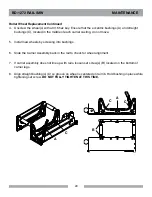
4.  Unscrew the wheel(s) with a 3/16 hex key. Ensure that the eccentric bushings (A) and straight  


bushings (C), located in the middle of each carrier casting, do not move.

5.  Install new wheels by screwing into bushings.

6.  Slide the Carrier Assembly back in the rail to check for wheel alignment. 

7.  If carrier assembly does not line up with rails, loosen set screw(s) (B) located on the bottom of 


carrier legs.

8.  Align straight bushing(s) (C) so groove on wheel is centered on rail rib. Hold bushing in place while 


tightening set screw. DO NOT FULLY TIGHTEN AT THIS TIME.

A

C

C

C

A

B

BD-1272 

RAIL 

SAW 

        MAINTENANCE

Summary of Contents for BD-1272

Page 1: ...tructions before using this equipment This manual MUST accompany the equipment at all times 04 2013 Revision 303 Manual Part No 165267 Barranca Diamond Products Inc 1315 Storm Parkway Torrance CA 9050...

Page 2: ...rself with the BD 1272 Rail Saw by reading and understanding this manual If you should have questions concerning your BD 1272 Rail Saw please feel free to call Barranca Dia mond at 310 523 5867 or tol...

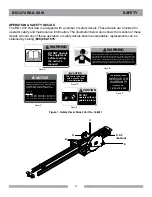
Page 3: ...clothing gloves neckties rings bracelets or other jewelry that may be caught in moving parts Non slip footwear is recommended Wear protective hair covering to contain long hair Hand protection plastic...

Page 4: ...work in a well ventilated area KEEP CHILDREN AWAY All visitors and children should be kept a safe distance from the work area Keep power cords disconnected when tool is not in use MAKE THE WORKSHOP K...

Page 5: ...CESSORIES AND PARTS Consult the owner s manual for recommended accessories and parts Using improper parts and accessories may increase the risk of personal and or bystander injury USE THE PROPER EXTEN...

Page 6: ...lly designed to filter out microscopic particles Where use of a dust extraction device is possible it should be used To achieve a high level of dust collec tion use an industrial vacuum cleaner SILICA...

Page 7: ...nderstood or if in doubt as to whether the tool is properly grounded Use only 3 wire extension cords that have 3 prong grounding plugs and 3 pole receptacles that accept the tool s plug Repair or repl...

Page 8: ...the product Do not use damaged extension cords Examine extension cords before using and replace if damaged Do not abuse extension cords and do not yank on any cord to disconnect Keep cords away from...

Page 9: ...0 150 250 Max Cord Length Max Cord Length Max Cord Length No 12 Wire No 10 Wire No 8 Wire 115v 230v NOTICE WARNING Grinding cutting drilling of masonry concrete metal and other materials with silica i...

Page 10: ...72 120V standard U ground electrical cord Saw comes complete with two sets of 72 rail rail connector plate 12 blade capacity cutting head two hold down clamps and standard garden hose water connector...

Page 11: ...leveled surface 2 Align ends of Rails 3 Slide Parallel Rail Support Brackets C from both ends of rail 4 Tighten screws until Brackets hold Rails firmly in place D 5 Repeat Step 1 through 4 if a lengt...

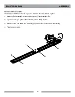
Page 12: ...e Connector Plate Assembly B 2 Tighten screws C lightly until connector plate is firmly seated 3 Slide the other half of the Rail Assembly D into the Rail Connector Assembly B 4 Fully tighten screws A...

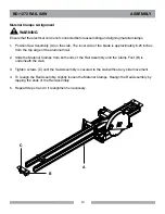
Page 13: ...sembly A until the Carrier Wheels C are over Rail Assembly B 3 Move the Cutting Head Assembly along the Rail Assembly with a sliding motion A B WARNING C Ensure that the power is disconnected before i...

Page 14: ...l Assembly until the Clamp Foot B is underneath the slab 3 Tighten screws C until the Saw Assembly is secured to the slab without any side movement 4 To realign the Rail Assembly slightly loosen the M...

Page 15: ...15 Hose Set Up 1 Connect Plastic Fitting A to Nipple B 2 Connect Hose Fitting C to Water Hose B A C BD 1272 RAIL SAW SET UP...

Page 16: ...the blade to the highest position and move the Saw Assembly to the beginning of the cut 2 Adjust the Valve B for the desired amount of water flow 3 Depress motor switch and lower the blade slowly int...

Page 17: ...system 2 Loosen the Tri Knob B Raise the blade to the highest position and move the Saw Assembly to the beginning of the cut 3 Adjust the Valve C for the desired amount of water flow 4 Depress motor s...

Page 18: ...ocated on the inner side of the blade Hold the wrench stationary Place wrench B on the Hex Screw at the end of the blade shaft Turn wrench B counter clockwise to remove the screw 4 Replace the blade a...

Page 19: ...lacement 1 Remove the Hex Screws A and Round Knob B 2 Remove Motor and Blade Guard Assembly from the Carrier Assembly 3 Remove Carrier Assembly from the Rail Assembly Place the Carrier Assembly on a f...

Page 20: ...wheels by screwing into bushings 6 Slide the Carrier Assembly back in the rail to check for wheel alignment 7 If carrier assembly does not line up with rails loosen set screw s B located on the bottom...

Page 21: ...ng s stationary while tightening down set screw s B lightly Groove aligns with center of upper rail rib Turn eccentric bushing until wheel groove lightly contacts upper rail rib Hold eccentric bushing...

Page 22: ...22 BD 1272 RAIL SAW exploded view...

Page 23: ...15A 152610 1 6 NIPPLE 1 4 NPT X CLOSE BRASS 159905 1 7 RAIL TRACK SAW 164926 4 8 FOOT RAIL 164944 4 9 CLAMP RAIL SAW MATERIAL 165113 2 10 ASSY RAIL CONNECTOR PLATE 165268 1 11 ASSY PARALLEL RAIL SUPPO...

Page 24: ...24 bd 1272 RAIL SAW exploded view...

Page 25: ...PS MACHINE 154657 6 7 KNOB BALL 2 3 8 16 INSERT 158519 1 8 SCREW 3 8 16 X 3 8 SOCKET HEAD SET CUP POINT 160713 6 9 CARRIER CART WHEEL COMP 164922 2 10 BASE INNER PIVOT 164923 1 11 BASE TRACK RAIL SAW...

Page 26: ...26 bd 1272 RAIL SAW exploded view...

Page 27: ...SPLIT LOCK 151747 2 3 WASHER 5 16 SAE FLAT 151754 2 4 FILTER MOTOR 157729 1 5 CAP MOTOR NO LOGO 157877 NL 1 6 CAP FILTER NO LOGO 157878 NL 1 7 SPACE CAP SCREW 157879 2 8 FLANGE 3 0 INNER 158106 2 9 SC...

Page 28: ...ASTIC 3 8 16X2 1 4 NO LOGO 56770 04 NL 1 4 TAG SERIAL BLANK 157500 1 5 DRIVE SCREW 7 X 5 16 ROUND HEAD 157849 2 6 SCREW HEX HEAD CAP M6 X 1 X 20MM 158158 4 7 WASHER SPLIT LOCK M6 158159 4 8 MANIFOLD W...

Page 29: ...bd 1272 RAIL SAW exploded view PARTS LIST Parallel Rail Support Bracket ITEM DESCRIPTION PART QTY 1 CLAMP UPPER RAIL 164939 1 2 CLAMP LOWER RAIL COMP 164942 1 3 SCREW 5 16 18X2 SOCKET HEAD CAP 165165...

Page 30: ...30 Rail Connector Plate ITEM DESCRIPTION PART QTY 1 PLATE RAIL CONNECTOR 164936 1 2 SHOE CONNECTOR COMP 164938 6 3 SCREW 5 16 18X2 SOCKET HEAD CAP 165165 6 bd 1272 RAIL SAW exploded view PARTS LIST...

Page 31: ...8X1 2 SOCKET HEAD CAP 156139 2 3 BASE MATERIAL CLAMP 165114 1 4 PLATE MATERIAL CLAMP SUPPORT 165115 1 5 STAND OFF THREADED 165116 2 6 FOOT MATERAL CLAMP 165117 2 7 SCREW 10 24 X 3 4 FLAT HEAD PHILLIPS...

Page 32: ...needed to maintain products and the replacement of components due to normal wear and tear are the purchaser s responsibility and are not covered by this Warranty All products or components replaced u...

Page 33: ...be replaced free of charge Blades and bits damaged due to careless or improper use are not covered under this war ranty Exclusions Barranca Diamond does not warrant the following components which carr...

Page 34: ...Distributor s name Then please call Barranca Diamond at 310 523 5867 or toll free at 800 630 7682 to obtain a Return Goods Authorization number RGA authorizing the return Please Note Ensure your item...

Page 35: ...35 NOTES...

Page 36: ...Barranca Diamond Products Inc 1315 Storm Parkway Torrance CA 90501 Toll Free 800 421 5830 Phone 310 539 5221 Fax 310 539 5158 www barrancadiamond com...

Reviews: