Chapter 3: BD CARV II Touch Pad Controller
49
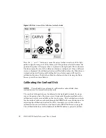
the screen is re-displayed. The calibration functions that are first displayed effect
the position of the FRAP iris and do not effect the confocal disk. The size of the
FRAP iris is not effected either. This positional adjustment is used for factory
calibration and has no optical effect. Calibration adjustments of the FRAP iris
can cause noise from the servo motor and therefore should not be changed.
In order to calibrate the position of the confocal disk, move it into the light path
with a serial command while the FRAP Iris Screen has the calibration function
activated. The iris graphic changes to a disk graphic and the calibration buttons
set the position of the confocal disk in the light path. When the confocal disk is
moved into the light path the calibrated confocal disk position is used.
Calibration adjustments to the confocal disk can also cause noise from the servo
motor and must be done carefully.
Calibrating the Filter Wheels
Because the positioning of the filters is so critical to an optimized light path, the
calibration of the filter wheels is done in a different manner. Like the other
calibration-equipped devices in the CARV II, each position of each filter wheel
has its calibration value stored in memory and each one can be adjusted
independently. Every CARV II is loaded with the same default values designed to
place each position in roughly the correct place. When each instrument is
calibrated during production, these positions may be modified to optimize
alignment. These new positions are stored in non-volatile memory with a
checksum. Each time the instrument is turned on, the memorized positions are
checked against the checksum. If this check should fail, the default values for all
positions of the failed filter wheel will be loaded and the appropriate wheel
screen will indicate that the default positions are implemented, as in Figure 3-11.


