background image

12

12

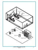
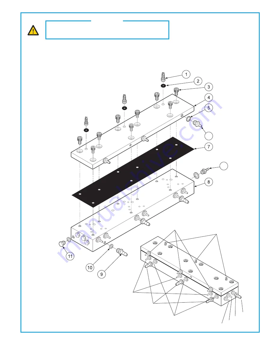
AUTOMATIC HANDPIECE CONTROL BLOCK

125-130

The automatic control block is the control center for your dental unit.


Individual handpiece pressure adjustments are located on the autoblock. To adjust the 

pressure to each handpiece:


a.  Turn adjustment screw 

clockwise

 to decrease the handpiece pressure.


b.  Turn adjustment screw 

counter-clockwise

 to increase the handpiece pressure.

CAUTION

When adjusting the handpiece pressure, do not over-

tighten the screws. Damage may result.

                      Drive Air In

              Out to Gauge

       Coolant Air In

Coolant Water In

Coolant Air Out

Drive Air Out

Coolant Water Out

Signal Air In

Handpiece Pressure 

Adjustment

12

6

ITEM 

1
2
3
4
5
6
7
8
9

10
11
12

PART DESCRIPTION
Adjusting  Stem ...............................
O-Ring, 021 ......................................
Screw, 6-32 x 1/4”...........................
Cap. ....................................................
Plastic Washer. ...............................
Barb, 10-32 x 1/16”.........................
Diaphram ........................................
Body ..................................................
Barb, 10-32 x 1/8”...........................
Plastic Washer, 1/4”.........................
Plug, 10-32  ......................................
Barb, 8-32 x 1/16”...........................

PART NUMBER

125-023
017-021
001-131
125-132
003-030
022-009
125-116
125-131
022-010
003-001
001-001
022-040

QTY

3
3
9
1
3
9
1
1
4

13

4
3

Summary of Contents for S-6307

Page 1: ...Service Manual S 6307 3 HP Automatic Euro Top Post Mount Doctor s System with Flex Arm Rev 5 1 10 20 900 021M...

Page 2: ...ubings do not become crimped or twisted 7 Remove the rigid arm end cap and tighten the cap screw to set the stop limits for the flex arm Replace the end cap 8 Install master valve assemblies with filt...

Page 3: ...ht side of the control head 6 Water coolant flow adjustments are located underneath the control head 7 Arm brake switch is located on the right side of the control head The brake is on when the toggle...

Page 4: ...e water relay valve More than one handpiece is operating A Handpiece is not all the way in the holder B Improper adjustment on pilot valve in the handpiece holder C Defective shuttle valve to gauge In...

Page 5: ...ggle Valve Screw 10 32 x 3 8 Holder Bar Needle Flow Valve Base Gauge Ferrule 1 4 Barb 10 32 x 1 8 Plastic Washer 1 4 Barb 10 32 x 1 16 Ferrule 1 8 Water Relay Indicator PART DESCRIPTION Momentary Valv...

Page 6: ...ment Screw 6 32 x 1 4 Head Knuckle Arm Fork Link Sleeve Seat Flex Arm Spring Adjustment Nut Nut Hex Jam 9 16 18 Nylon Insert Collar w Shoulder Brake Flex Brake Pad PART DESCRIPTION Piston Brake U Cup...

Page 7: ...ITEM 1 2 3 4 5 6 7 8 9 PART DESCRIPTION Flex Arm Thrust Washer Small End Cap Set Screw Half Dog Rigid Arm Pivot Mount Snap Ring Plug Square 3 4 Bronz Bushing PART NUMBER 106 336 003 038 106 326 005 00...

Page 8: ...ty Center Kit Plug 10 32 Screw 6 x 3 4 Plastic Washer 1 4 Plug 3 4 Plug 1 3 8 Plug 1 2 Plug 1 1 2 Plug 2 1 4 Plug 13 16 Barb 10 32 x 1 16 Barb 10 32 x 1 8 Ferrule 1 8 PART NUMBER 144 005 020 022 127 0...

Page 9: ...8 8 UTILITY CENTER INSTALLATION 144 018...

Page 10: ...Washer 1 4 Barb 10 32 x 1 8 O Ring 001 Stem O Ring 003 Spring O Ring 007 PART DESCRIPTION Plug Barb 10 32 x 1 16 Cap Inlet Filter Element 100 Micron O Ring 018 Filter Element 35 Micron Gauge Piston G...

Page 11: ...g 004 Spring O Ring Body Plastic Washer 1 4 Barb 10 32 x 1 8 Plug O Ring 001 Stem O Ring 003 PART DESCRIPTION Spring O Ring 007 Plug Cap Inlet Filter Element 100 Micron O Ring 018 Filter Element 35 Mi...

Page 12: ...40 x 5 8 Body Piston Diaphragm Cap Screw 6 x 1 2 Barb 10 32 x 1 16 Plastic Washer 1 4 Valve Body Spring O Ring 002 O Ring 001 Stem PART NUMBER 123 018 005 028 123 013 123 014 127 031 123 012 001 267 0...

Page 13: ...When adjusting the handpiece pressure do not over tighten the screws Damage may result Drive Air In Out to Gauge Coolant Air In Coolant Water In Coolant Air Out Drive Air Out Coolant Water Out Signal...

Page 14: ...ION Ring Cover Spring Stem Includes 017 012 o ring Body Poppet Spring O Ring 013 Baseplate Screw 4 40 x 1 4 Rubber Pad Screw 6 32 x 1 4 PART NUMBER 126 202 126 201 008 005 126 005 126 004 126 006 008...

Page 15: ...ead Water 40 psi Optional Water Bottle System Mini Regulator 128 016 On Off Toggle 120 000 Air Regulator 127 010 A Water Regulator 127 010 W Syringe Handpiece 2 Handpiece 3 Handpiece 1 Unregulated Foo...

Page 16: ...anty All warranty is limited to repair or replacement by BDS Products returned to the factory and determined to be defective will be repaired or replaced free of charge at discretion of BDS The warran...

Page 17: ...Beaverstate Dental Inc 115 S Elliott Rd Newberg OR 97132 800 237 2303 503 538 8756 503 538 2845 Fax www beaverstatedental com...

Reviews: