background image

7

ONLY

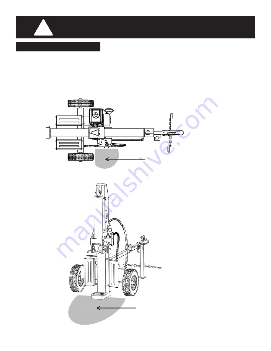
 operate the log splitter from the operator zone as shown in the diagrams below. The operator has the safest 

and most efficient access to the control valve and the beam in this location. Operating the log splitter in another 
location can result in serious injury or death.

OPERATOR ZONE

IMPORTANT SAFETY INFORMATION

!


ONLY 

operate the log splitter from the operator zone as shown in the diagrams below. The operator has the safest and 

most efficient access to the control valve and the beam in this location. Operating the log splitter in another location can 
result in serious injury or death.

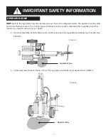
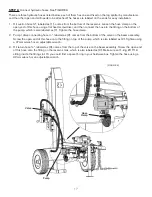
a. Horizontal Operating Position: Stand on the control lever side of the log splitter and stabilize log if needed. See 

FIGURE 1.

b. Vertical Operating Position: Stand in front of the log splitter and stabilize log if needed. See FIGURE 2.


GENERAL REPAIR


OPERATOR ZONE


Operator Zone 


(FIGURE 1).


Operator Zone 


(FIGURE 2).


Page 7


Summary of Contents for Agri Ease BE-25TLE65GX

Page 1: ...MANUAL BE LS25TLE5GC BE 25TLE65GX ASSEMBLY OPERATING INSTRUCTIONS Purchase Date ____________ Model NO _____________ Serial NO ______________ Dealer ___________________________________________________...

Page 2: ...dels We reserve the right to change product specifications designs and equipment without notice and without incurring obligation All the power testing information used to establish the power rating of...

Page 3: ...afety 10 Assembly Set Up Instructions 11 22 Unpacking the Container 11 12 Assembling 13 19 Set Up 20 21 Know Controls and Features 22 Operating Instructions 23 26 Starting and Stopping the Machine 23...

Page 4: ...nd birth defects or other reproductive harm DANGER This machine was built to be operated according to the safe operation practices in this manual As with any type of power equipment carelessness or er...

Page 5: ...2677 for replacement decals SAFETY DECALS Page 2 Part 410 188 Part 410 249 Part 410 237 Part 410 233 Part 410 647 Make sure that all safety warning decals are in good condition and readable Always re...

Page 6: ...ar nonslip heavy duty protective gloves when operating this product WEAR SAFETY FOOTWEAR Always wear nonslip steel toed safety footwear when operating this product WARNING GASOLINE IS FLAMMABLE Allow...

Page 7: ...tion to the following instructions at all times a Do not check for leaks with your hand b Do not operate machine with frayed kinked cracked or damaged hoses fittings or tubing c Stop the engine and re...

Page 8: ...dard safety glasses with side shields Always use eye protection which is marked to comply with ANSI Z87 1 1 BEFORE operating this log splitter make sure that you wear safety gear such as goggles or sa...

Page 9: ...urn until it leans against the beam and is stable b When splitting extra large or uneven logs the log must be stabilized with wooden shims or split wood placed between the log and end plate or ground...

Page 10: ...the operator zone as shown in the diagrams below The operator has the safest and most efficient access to the control valve and the beam in this location Operating the log splitter in another locatio...

Page 11: ...can be almost invisible Escaping fluid under pressure can have sufficient force to penetrate skin causing SERIOUS INJURY or even DEATH Leaks can be safely detected by passing a piece of cardboard ove...

Page 12: ...e 5 minutes before starting the engine 10 ALWAYS replace the gas cap securely Never remove gas cap while the engine is hot or running 11 To prevent fires clean debris and chaff from the engine and muf...

Page 13: ...tions 8 ALWAYS be careful when backing up with your log splitter in tow It could jackknife 9 ALWAYS allow for added length of your log splitter when turning parking and crossing intersections and in a...

Page 14: ...tion or modification is misuse and could result in a hazardous condition leading to possible serious personal injury WARNING Do not connect to power supply until assembly is complete Failure to comply...

Page 15: ...and then place aside carefully for assembly Step 5 Use a pry bar or claw hammer to remove the plywood splinters securing the beam and tank assemblies on the crate bottom Take out the two heavy assembl...

Page 16: ...nd x 1 Page 10 NOTE Due to the weight size of the log splitter it s recommended that two or more adults be present to assist with the assembling Some lifting tools such as hoist crane jack etc are rec...

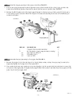
Page 17: ...d bolt M10 x 75 2 5 2 Flat washer M10 4 5 3 Lock nut M10 2 STEP 3 Assemble the pump assembly to the engine See FIGURE 6 1 Remove the engine from its box and place it on a level stable surface and tap...

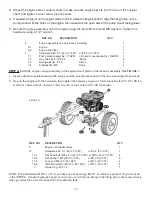
Page 18: ...15 Page 12 3 Adjust the engine side of coupler shaft to make sure the engine key fits into the slot of the coupler shaft and tighten the set screw just loosened 4 If needed slowly ull on the engine st...

Page 19: ...ng and lowering the beam as it is very heavy Have a helper support the beam as you perform the following steps Be sure to keep hands away from any possible pinch points 2 Remove the clevis pin and spr...

Page 20: ...g in your hardware box Tighten the hose using a 32mm wrench or an adjustable wrench Page 14 STEP 6 Connect hydraulic hoses See FIGURE 9 There are three hydraulic hoses listed below each of them has on...

Page 21: ...nch on the lock nuts STEP 7 Install the log tray assemblies See FIGURE 10 1 Lower the beam to horizontal position Please refer to Beam Operating Positions section in Page 23 2 Position the log tray fr...

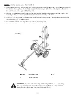
Page 22: ...handle up into the operating position and secure with the clevis pin and cotter pin just removed EP 8 Assemble the control handle See FIGURE 11 The control handle is shipped hanging from the valve on...

Page 23: ...indoors or while the engine is hot or running Page 17 Gas and Oil Fill Up Service the engine with gasoline and engine oil as instructed in the engine manual packed with your log splitter Read the inst...

Page 24: ...However you MUST check the fluid level before each operating If not filled proceed with above steps FIGURE14 Page 21 ISO 68 ISO 46 ISO 32 ISO 22 Please select the oil based on the outside temperature...

Page 25: ...end plate holds the log in place while the wedge splits the log FIGURE15 Cylinder Tongue Flip down Stand Log Tray End Plate Horizontal Beam Lock Splitting Wedge Control Handle Log Dislodger NOTE This...

Page 26: ...our hands to lift up the beam and flip it over to the vertical position then rotate the horizontal lock lever back up the tongue to release the lock 5 To place the beam in the Horizontal Position proc...

Page 27: ...d the wedge stops moving forward NEUTRAL To stop wedge Release the control handle or move the lever to the NEUTRAL position to stop the wedg movement REVERSE To return the wedge Engage the control han...

Page 28: ...on the side of the log See FIGURE 19 WARNING Never place your hand on the ends of the log between the log and the end plate or the log and the splitting wedge WARNING Only one operator permitted The...

Page 29: ...nd up to transporting position 1 Pull out the lock handle of the stand and rotate it up The stand will be secured horizontally with the tongue automatically Please refer to FIGURE 5 on page 14 2 Have...

Page 30: ...etween the engine and the pump contact an authorized dealer or Boss Industrial Inc Make sure to change a new coupler spider immediately when the coupler spider fails completely or you will experience...

Page 31: ...ting it with a light oil or silicone A log splitter cover from the manufacturer is recommended FIGURE21 FIGURE22 Page 28 5 Refill the reservoir tank Please follow the steps in Page 22 to fill the tank...

Page 32: ...or bleed air 6 Drain oil clean reservoir and refill 7 See authorized service dealer 8 See authorized service dealer Leaking Cylinder 1 Worn seals 2 Scored cylinder 1 See authorized service dealer 2 S...

Page 33: ...50 Maximum Log Length 24 in 24 in Wedge Height 7 in 7 in Cycle Time Forward 7 seconds 7 seconds Reverse 5 seconds 5 seconds Wheels 16 x 4 8 x 8 in 16 x 4 8 x 8 in Hydraulic Capacity 4 gallons 4 gallon...

Page 34: ...31 EXPLODED DIAGRAM PARTS LIST Page 28 EXPLODED DIAGRAM PARTS LIST Page 31...

Page 35: ...ydraulic Valve 1 14 2 520 452 Control Handle 15 220 Ball Grip 1 15 1 560 454 Connecting Hydraulic Hose w Protection Spring 900 1 15 2 730 619 O Seal Ring 15 1 9 1 16 1 730 088 O Seal Ring 24 2 4 2 16...

Page 36: ...1 44 710 877 Oil Drain Screw PH M16 15 1 45 730 064 O Seal Ring 20 2 4 1 46 1 540 049 Suction filter 45 Degree Adapter Hex32 1 46 2 730 122 O Seal Ring 30 3 1 1 47 560 342 Oil Suction Hose 24 300 Curv...

Page 37: ...520 Hex Head Bolt ZP M10 25 8 8 8 94 750 525 Flat Washer ZP M10 16 95 720 120 Lock Nut ZP M10 8 96 320 926 Log Dislodger R 1 97 320 927 Log Dislodger L 1 98 710 511 Hex Head Bolt ZP M12 45 8 8 4 99 75...

Page 38: ...x 2 Wheel x 2 Hardware kit 2 5 6 1 8 Instruction manual x 1 Hardware kit box 1 including PACKING LIST OWNERS MANUAL BE LS25TLE5GC BE 25TLE65GX ASSEMBLY OPERATING INSTRUCTIONS Purchase Date ___________...

Page 39: ......

Reviews: