14
STEP 2:
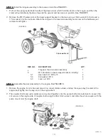
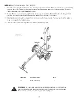
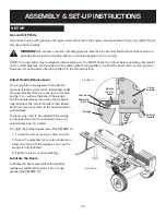
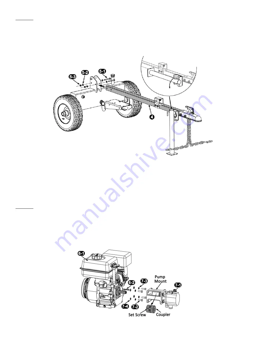
Install the tongue assembly to the reservoir tank. See FIGURE 5.
1. Pull out the spring loaded lock handle of flip-down stand which hold the stand on the tongue, and then the
stand will automatically flip down towards the ground and be secure in position. See FIGURE 5.
2. Remove the M10 hardware from the beam support bracket on the tank using a 16mm wrench for bolts and a
17mm wrench for the lock nuts. Attach the tongue to the reservoir assembly and screw on the hardware just
removed and tighten.
STEP 3:
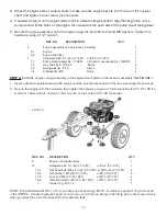
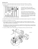
Assemble the pump assembly to the engine. See FIGURE 6.
1. Remove the engine from its box and place it on a level stable surface, and tap the square key (located in the
engine box) tightly into the key slot on the engine shaft.
2. The coupler shafts and nylon spider were mounted together onto the pump shaft at manufacturer’s. Loosen the
set screw on the engine side of coupler shaft using the 3mm Allen wrench, and slide the whole coupler with the
pump mount onto the engine shaft.
Page 11
STEP 2:
Install the tongue assembly to the reservoir tank.
See FIGURE 5.
.
1. Pull out the spring loaded lock handle of flip-down stand which hold the stand on the tongue, and then the stand will
automatically flip down towards the ground and be secure in position. See FIGURE 5.
2.
Remove the M10 hardware
from the beam support bracket on the tank
using a 16mm wrench for bolts and a 17mm
wrench for the lock nuts
.
Attach the tongue to the reservoir assembly and screw on the hardware just removed and
tighten.
REF. NO. DECSRIPTION
QTY.
4
Tongue & Flip-down stand assembly
1
5
M10 Hardware on beam support bracket, including:
1
5-1
Hex head bolt / M10 x 75
2
5-2
Flat washer / M10
4
5-3
Lock nut / M10
2
STEP 3:
Assemble
the pump assembly to the engine. See FIGURE 6.
1. Remove the engine from its box and place it on a level stable surface, and tap the square key (located in the engine
box) tightly into the key slot on the engine shaft.
2. The coupler shafts and nylon spider were mounted together onto the pump shaft at manufacturer’s. Loosen the set
screw on the engine side of coupler shaft using the 3mm Allen wrench, and slide the whole coupler with the pump
mount onto the engine shaft.
Stand Lock
(FIGURE 5)
Flip-down Stand
Page 14
(FIGURE 6)


