11
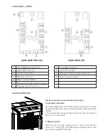
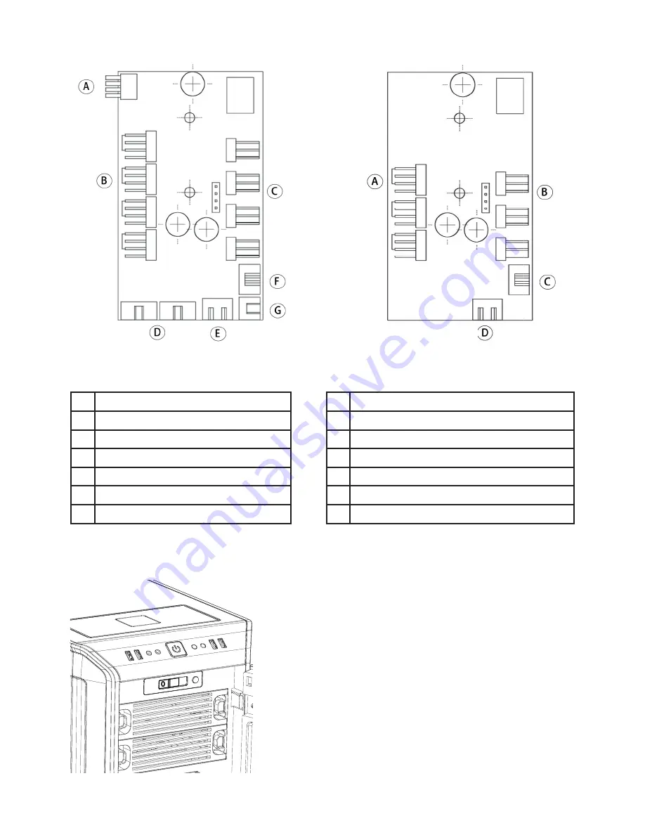
4.3 PCB PANEL / PORTS
A
4-Pin PWM Connector to M/B
A
4-Pin PWM Connector
B
4-Pin PWM Connector
B
3-Pin Fan Connector
C
3-Pin Fan Connector
C
Fan Speed Controller Switch Connector
D
LED Strip Connector
D
Power Connector (SATA)
E
Power Connector (SATA)
F
Fan Speed Controller Switch Connector
G
QI Charger Power Connector
4.4 FAN CONTROLLER
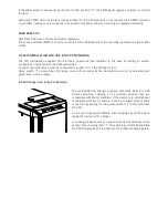
The fan controller has two modes of operation.
1. Automatic operation
For this the PWM signal of the MB is used and the speed of all fans
connected (PWM and 3-pin) can be adjusted automatically through
the MB.
In this mode the fan controller slider switch must be set to the fi rst
position “0” on the far left.
2. Manual control
When the fan controller slider switch is moved from its fi rst
position “0” to the right, the PWM signal is dropped and the fan
speed can be regulated manually.
DARK BASE PRO 900
DARK BASE 900


