background image

Page 2 of 12 


75.5897.02 LZR-H110 20170821

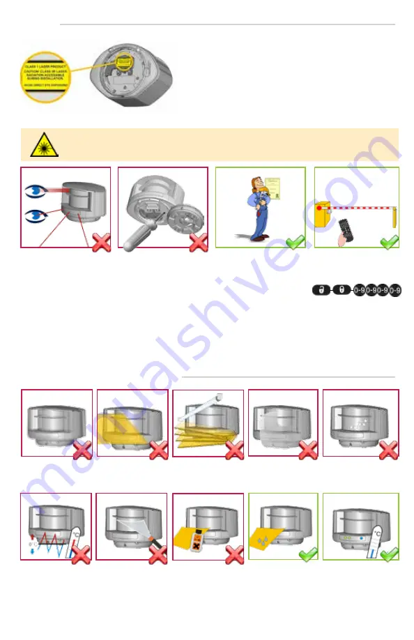
The device contains IR and visible laser diodes.

IR laser: wavelength 905nm; max. output pulse power 75W 

(Class 1 according to IEC 60825-1)

Visible laser: wavelength 650nm; max. output CW power 3mW 

(Class 3R according to IEC 60825-1)

The visible laser beams are inactive during normal functioning.

The installer can activate the visible lasers if needed.

CAUTION!


Use of controls, adjustments, or performance of procedures other than those specified herein 

may result in hazardous radiation exposure.

INSTALLATION AND MAINTENANCE

Avoid extreme

vibrations.

Do not cover 

the front screens.

Avoid moving objects 

and light sources in 

the detection field.

Avoid condensation.

Avoid the presence 

of smoke and fog in 

the detection field.

Avoid exposure to 

sudden and extreme 

temperature changes.

Keep the sensor 

permanently powered 

in environments where 

the temperature can 

descend below 0°C.

Wipe the front 

screens regularly 

with a clean and 

damp cloth.

Do not use aggressive 

products to clean 

the front screens.

Avoid direct exposure 

to high pressure 

cleaning.

Do not look into the laser 

emitter or the visible red 

laser beams.

The warranty is void if 

unauthorized repairs are 

made or attempted by 

unauthorized personnel. 

Only trained and qualified 

personnel are recommended 

to install and set up the 

sensor. 

After installation, enter an 

access code by remote 

control.

This sensor is designed to be used as a movement and presence detector to initiate the opening and the closing 

process of a gate or a barrier. Other use of the device, especially on industrial doors, is outside the permitted purpose 

and cannot be guaranteed by the manufacturer and might infringe the following patent application EP 1 470 314 B1.

The manufacturer of the system is responsible for installing the sensor and the system in compliance with applicable 

national and international regulations and standards on safety and if applicable, the machinery directive 2006/42/EC.

The manufacturer of the sensor cannot be held responsible for incorrect installations or inappropriate adjustments of 

the sensor.

SAFETY

Page 2 of 12 


75.5897.02 LZR-H110 20170821

OBSOLETE

Summary of Contents for LZR-H110

Page 1: ...7 02 LZR H110 20170821 Page 1 of 12 LZR H110 EN LASER SCANNER FOR BARRIERS GATES with max detection range of 5 0 m x 6 5 m 16 5 ft x21 ft User s Guide 75 5897 02 LZR H110 20170821 Page 1 of 12 O B S O L E T E ...

Page 2: ... use aggressive products to clean the front screens Avoid direct exposure to high pressure cleaning Do not look into the laser emitter or the visible red laser beams The warranty is void if unauthorized repairs are made or attempted by unauthorized personnel Only trained and qualified personnel are recommended to install and set up the sensor After installation enter an access code by remote contr...

Page 3: ...lock 2 5 connector 6 protection cover 7 visible laser beam 3 8 notch for tilt angle adjustment 2 9 adjustable bracket 1 Detection LED relay 1 opening field 2 Detection LED relay 2 safety field 3 Error LED 4 Power LED Remote control sequence Possible remote control adjustments Factory values LED flashes slowly All 4 LEDs can be switched off and on again by remote control This can be useful in cases...

Page 4: ...after unlocking you need to enter an access code from 1 to 4 digits X NUMBER OF FLASHES VALUE OF THE PARAMETER field width 4 2 m field width is defined by teach in To end an adjustment session always lock the sensor Enter the existing code ADJUSTING ONE OR MORE PARAMETERS CHECKING A VALUE RESTORING TO FACTORY VALUES SAVING AN ACCESS CODE DELETING AN ACCESS CODE HOW TO USE THE REMOTE CONTROL Page 4...

Page 5: ...connector and position the cable in the slit 40 cm recommended lmin mm hmin mm d mm distance between laser and opening 50 100 150 200 240 360 480 600 52 59 66 73 side view front view POWER SUPPLY POWER SUPPLY RELAY 1 OPENING FIELD RELAY 2 SAFETY FIELD NOT USED RED BLACK WHITE GREEN WHITE BLACK GREEN WHITE BLUE BLUE WHITE ORANGE ORANGE BLACK TEST TEST No test function connect blue and blue white wi...

Page 6: ...After 15 minutes the beams switch off Verify the lateral position of the sensor Make sure the laser beam is visible on the opposite pole Verify if both beams are on equal height WITH REFERENCE POINT surface of min 15 cm The sensor will automatically adjust the safety field on the basis of the reference point if C 00 WITHOUT REFERENCE POINT left right left right Choose the correct mounting side LEF...

Page 7: ...sensor has finished the teach in make sure that the safety field is correctly configured and that the area around the barrier or gate is safe You can increase or decrease the field by 10 cm The safety field can be adapted more precisely by launching a teach in the sensor learns the environment Before launching a teach in make sure that the selected field size is bigger than the desired field size ...

Page 8: ...he walk path and stores this as a new detection field The shortest distance measured by each laser beam is stored by the sensor and determines the field limit You can increase or decrease the field by 10 cm The opening field can be adapted more precisely by launching a teach in the sensor learns the environment Before launching a teach in make sure that the selected field size is bigger than the d...

Page 9: ...TMENTS bidirectional detection approaching and going away BIDIRECTIONAL unidirectional detection only approaching in any direction 400 CENTER unidirectional detection only approaching towards the barrier gate 200 CENTER unidirectional detection only approaching within width of barrier gate 100 CENTER unidirectional detection only approaching towards central zone of barrier gate 50 CENTER unidirect...

Page 10: ... or presence presence presence presence motion presence RELAY 1 RELAY 2 R1R2 MAGIC WAND teach in safety field visible laser beams teach in opening field factory values OUTPUT CONFIGURATION A NO P NC P NC A NO P NC A NO P NC A NO RELAY 1 RELAY 2 R1R2 A active P passive FACTORY VALUES Page 10 of 12 75 5897 02 LZR H110 20170821 O B S O L E T E ...

Page 11: ...lue 3 or 4 Launch a new teach in Sensor is masked Verify and clean the front screens with a damp cloth Orange LED is on Power supply voltage exceeds acceptable limits Check power supply voltage Sensor exceeds temperature limits Verify the temperature of the environment Protect the sensor from sunlight using a cover if necessary Internal error Wait a few seconds If the LED remains ON reset the powe...

Page 12: ...Original Instructions BEA the sensor manufacturer cannot be held responsible for incorrect installations or inappropriate adjustments of the sensor device therefore BEA does not guarantee any use of the sensor outside of its intended purpose BEA strongly recommends that installation and service technicians be AAADM certified for pedestrian doors IDA certified for doors gates and factory trained fo...

Reviews: