75.5897.02 LZR-H110 20170821
Page 5 of 12
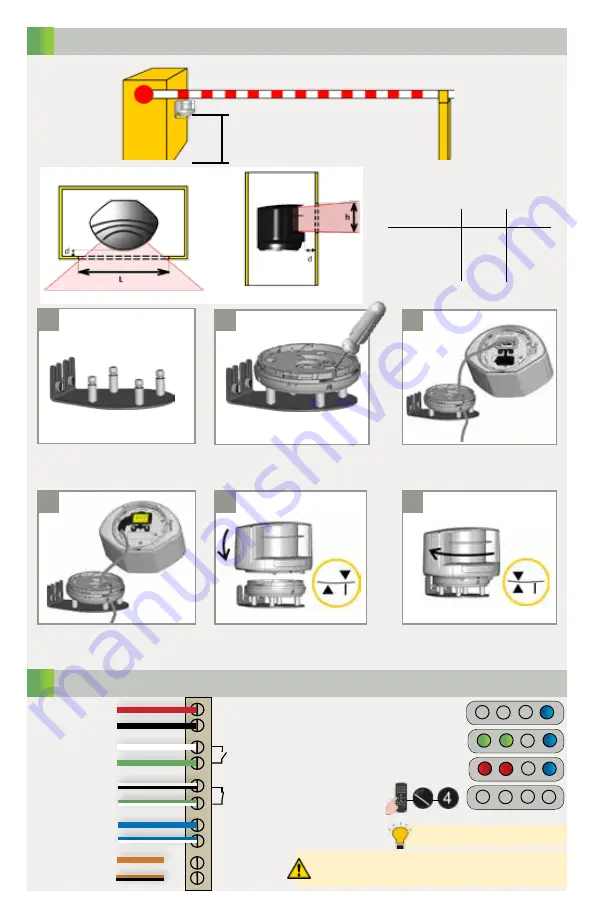
MOUNTING
WIRING
1
2
a
d
b
e
c
f
Use the LBA mounting support
for installation on the pole.
Position the bracket and secure
using the 4 screws to avoid
vibrations.
Close the protection cover and
secure it.
Rotate the sensor until the two
triangles are face to face.
Position the housing on the
bracket.
Open the protection cover, plug
the connector and position the
cable in the slit.
40 cm
(recommended)
l
min
(mm) h
min
(mm)
d (mm)
distance between
laser and opening
50
100
150
200
240
360
480
600
52
59
66
73
side view
front view
POWER
POWER SUPPLY -
RELAY 1 - OPENING FIELD
RELAY 2 - SAFETY FIELD
NOT USED
RED
BLACK
WHITE
GREEN
WHITE/BLACK
GREEN/WHITE
BLUE
BLUE/WHITE
ORANGE
ORANGE/BLACK
TEST +
TEST -
No test function:
connect blue and blue/white wires to power supply
(no polarity)
The sensor tests both relays.
Power on with test
No detection
Detection on both relays
75.5897.02 LZR-H110 20170821
Page 5 of 12
OBSOLETE


