1
2
Page 2 of 4
75.5996.03 MS41 20210421
9
When wiring multiple devices together to create a system configuration, it is best to ensure that each device works
independently. This will reduce troubleshooting if a discrepancy occurs.
9
Prior to installing any equipment in either new or existing circuits, verify correct line voltage and line stability.
Always remember to shut off the power before performing circuit wiring.
9
Do not place the sensor in the door’s opening range, where the sensor may see door movement.
9
Do not place moving objects in front of the sensor.
INSTALLATION TIPS
WIRING
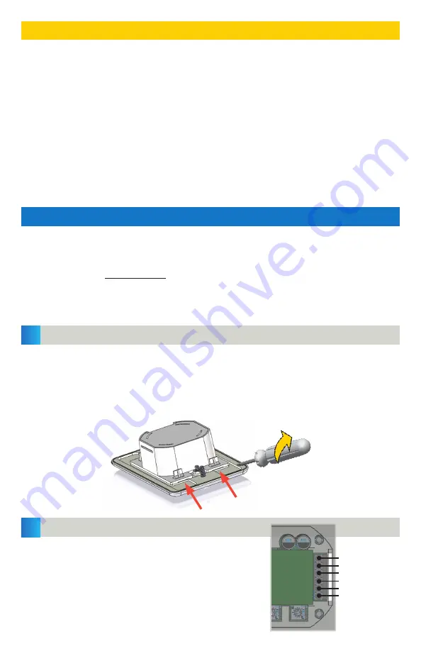
REMOVE FACE PLATE
Wire the MS41 to the door control according to the
diagram shown here.
NOTE: Use either N.O. or N.C.
–
not both. Refer
to the door control manual to determine which
must be used.
Detach the face plate from the cube by inserting a flathead screwdriver into one of the
snap fittings and twisting to loosen from the face plate (see image below). Repeat on
the nearby snap fitting located on the same side, top or bottom.
You may loosen the cube from the plate on either the top or bottom. Only two snap
fittings must be loosened.
empty
N.C.
N.O.
COM
12
–
24 VAC/VDC
12
–
24 VAC/VDC
PRECAUTIONS
Shut off all power going to header before attempting any wiring procedures.
Maintain a clean and safe environment when working in public areas.
Constantly be aware of pedestrian traffic around the door area.
Always stop pedestrian traffic through the doorway when performing tests that may result in unexpected reactions by the
door.
ESD (electrostatic discharge)
: Circuit boards are vulnerable to damage by electrostatic discharge. Before handling any
board, ensure you dissipate your body’s ESD charge.
Always check placement of all wiring before powering up to ensure that moving door parts will not catch any wires and
cause damage to equipment.
Ensure compliance with all applicable safety standards (i.e. ANSI A156.10) upon completion of installation.
DO NOT attempt any internal repair of the components. All repairs and/or component replacements must be performed by
BEA, Inc. Unauthorized disassembly or repair:
1. May jeopardize personal safety and may expose one to the risk of electrical shock.
2. May adversely affect the safe and reliable performance of the product resulting in a voided warranty.
Recommended:
22
–
26 AWG


