BeagleBone DVI-D with
Audio Cape
System Reference Manual
Revision A1
Page 24 of 28
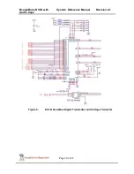
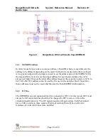
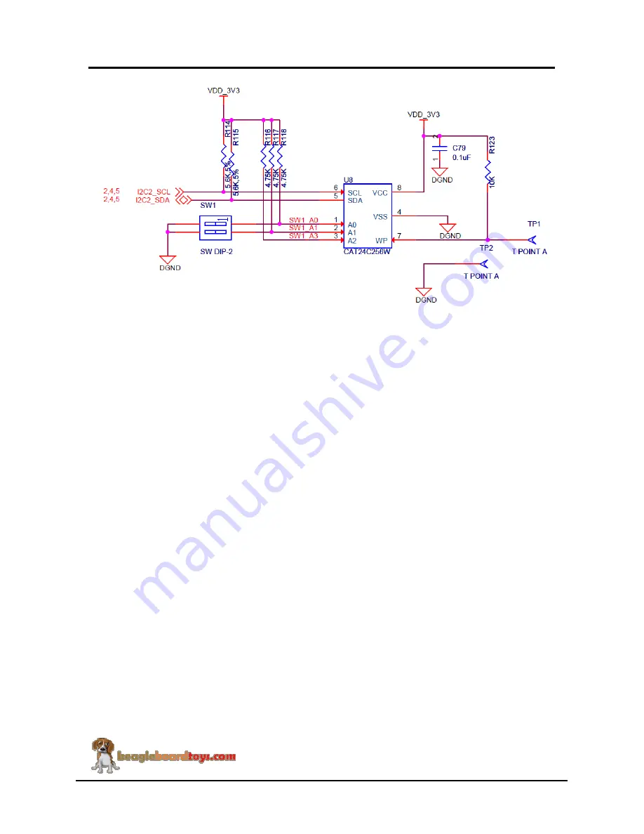
Figure 9.
BeagleBone DVI-D with Audio Cape EEPROM
5.4.1
EEPROM Address
In order for each Cape to have a unique address, a board ID scheme is used that sets the
address to be different depending on the order in which it is stacked onto the main board.
A two position dipswitch or jumpers is used to set the address pins of the EEPROM. It is
the responsibility of user to set the proper address for each board. Address line A2 is
always tied high. This sets the allowable address range for the expansion cards to 0x54 to
0x57.All other I2C addresses can be used by the user in the design of their Capes. But,
these addresses must not be used other than for the board EEPROM information.
5.4.2
I2C Bus
The EEPROMs on each expansion board is connected to I2C2. For this reason I2C2 must
always be left connected and should not be changed by SW to remove it from the
expansion header pin mux. The I2C signals require pull-up resistors. Each board must
have a 5.6K resistor on these signals. With four resistors this will be an affective
resistance of 1.4K if all Capes were installed.

