background image

RST-100 INSTALLATION AND CONFIGURATION MANUAL 


45 


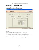
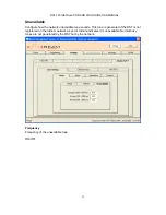
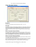
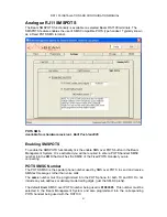
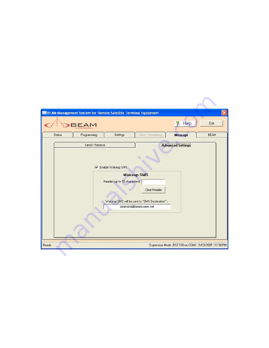
Advanced Message Settings


This tab enables specialised setting of a wake up SMS message for specific applications. 

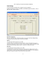
When the Enable Wake up SMS is ticked every time the units is power cycled this will 
automatically send a status SMS message to the predetermined address/destination 
 
The Destination address is the address that has been setting the message settings tab. 
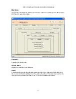
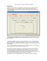
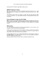
Wakeup Header


The wakeup header enables up to 10 characters to be entered at the start of the wake-up 
SMS. For example [Loc MELB01 ]


Summary of Contents for RST100

Page 1: ...RST 100 INSTALLATION AND CONFIGURATION MANUAL 1 Remote Satellite Terminal RST100 Configuration Beam Management System Manual Beam Communications Pty Ltd ...

Page 2: ...ies which may result from its use No license is granted by implication or otherwise under any patent or patent rights of Beam Beam reserves the right to change specifications at any time without notice Copyright 2004 Beam Communications Pty Ltd All rights reserved Note The SMS_POTS Functionality is only available on RST100 terminals with the following serial number type Serial Numbers 100AXXXX The...

Page 3: ... 16 RST Last Configuration 16 RST State 17 SIM MSISDN 17 LBT IMEI 17 LBT Firmware 17 UTC Time 17 Temperature 17 Input Voltage 17 RST Error Count 17 Temperature 17 Signal 17 LOGS 18 Fetch Log 18 Clear Log 18 Export Log 18 Error Logs 18 Error codes 19 PROGRAMMING MENU 20 SECURITY MENU 20 Supervisor PINS 20 Change RST Supervisor PIN 20 User PINS 21 Change RST User PIN 21 FIRMWARE MENU 21 Flash Upgrad...

Page 4: ...ALL MODE 28 CTS de assert 29 CTS Handling 29 RI ON INCOMING DATA CALLS 29 SIM SMSC SETTINGS 30 Disables PIN lock 30 SMSC SMS Gateway Number 30 ANALOG RJ11 POTS SETTINGS 31 Line Settings Tones Ringer 31 Frequency 31 1st ON 2nd ON 1st OFF 2nd OFF 31 Dial tone 32 Frequency 32 Frequency of the dial tone 32 ON OFF timers 32 Stutter 32 Unavailable 33 Frequency 33 ON OFF 33 Gain Settings 34 Dial Tone Sig...

Page 5: ...MBERS 40 Emergency 40 Voicemail 40 Iridium Translation Voicemail Number 40 Iridium Translation Emergency Number 40 ANALOGUE RJ11 SMSPOTS 41 Enabling SMSPOTS 41 POTS SMSC Number 41 SMSPOTS Number Prefixes 42 Using Intelligent Handset with POTS SMS 42 SMS mailbox 42 MESSAGE 43 SMS destination 43 Send SMS 43 Send SBD 44 Priority 44 Read Last SMS 44 Delete Last SMS 44 Wakeup Header 45 SENDING REMOTE S...

Page 6: ...ng specific Menu items of the unit during routine operation when required Accessing these menu items is best performed using the Beam Management System BMS This section covers most of the items that can be configured in the Supervisor Menu of the BMS The following section will cover 1 Installation of the BMS software on your PC 2 Using the BMS 3 Configuration Menu Items ...

Page 7: ...Management System software must be installed on your PC Laptop Once the BMS is installed you will then connect from your PC to the LOG Port of the RST100 Installing the BMS Software on your Computer The install package comes with 3 files 1 Setup exe 2 BMS CAB 3 Setup lst To start the install double click on Setup exe ...

Page 8: ...RST 100 INSTALLATION AND CONFIGURATION MANUAL 8 If flash magic is not already installed then the install will automatically start Accept the licence agreement ...

Page 9: ...RST 100 INSTALLATION AND CONFIGURATION MANUAL 9 Select directory to install files Select Start Menu folder ...

Page 10: ...RST 100 INSTALLATION AND CONFIGURATION MANUAL 10 Do not create desktop or Quick Launch icon ...

Page 11: ...RST 100 INSTALLATION AND CONFIGURATION MANUAL 11 Do not Launch Flash Magic or view the Release notes OK to finish install ...

Page 12: ...RST 100 INSTALLATION AND CONFIGURATION MANUAL 12 Launching BMS From the Start Menu Select Programs Beam Management System Select Beam Management System ...

Page 13: ...Run the Beam Management System from the start bar To access the Supervisor Menu of the terminal through the BMS follow these steps 1 Reset the RST100 terminal pressing the red reset button on the unit or alternatively power cycle the unit This will ensure the PC recognises the terminal ...

Page 14: ...atically From time to time you may need to restart your computer as some Comm ports on PC s are not as reliable as others 4 Once the Terminal is found in the display window press OK you will then be able to access the terminal settings and configuration menus 5 The BMS will request your Supervisor PIN in order to access this menu you must enter the default PIN of 3170 unless it has been previously...

Page 15: ...any of the parameters if not configured correctly or in line with the purpose for which they are intended will affect the performance of the terminal 2 The Supervisor Menu allows control and access to all the following Menu items 3 The RST100 is capable of being loaded with new firmware in the field so some items on the RST Supervisor Menu may change as software is upgraded It is probable you will...

Page 16: ...es a full analysis of the following items The data can provide a Refresh the status at anytime RST100 Status Menu RST Firmware Shows current Firmware Version of the RST100 RST PCB Shows the PCB Circuit Board Revision inside the terminal RST Serial Number Shows the Serial Number of the terminal RST Last Configuration Shows last time Configuration changes were made ...

Page 17: ...he Transceiver module LBT Firmware Shows the Firmware Version of the LBT module UTC Time Displays Current UTS Time Temperature Shows the current terminal temperature Input Voltage Shows the current input voltage to the terminal RST Error Count Counter of errors reported Temperature Shows the Firmware Version of the LBT module Signal Each Bar Represents signal rating out of 5 ...

Page 18: ...as tracking any error messages or SMS messages sent from the terminal Fetch Log The Call log can be cleared and retrieved from this menu option within the BMS To get the Log press the Fetch Log button Clear Log To Clear Log Press the Clear Log Memory Tab Export Log Press the Export Log button to export the Log to a text file Error Logs The Log also logs any unexpected errors that occur on the RST ...

Page 19: ...rtant SMS error code as PIN 3 An equipment error reported from the LBT ME error code as PIN 4 Over temperature alarm from RJ11 line interface 5 ROM checksum error on RST firmware Continued correct operation in doubt 6 The RST has had to hardware reset the LBT due to a lack of response Can occur if LBT serial port locks up 7 Short Burst Data sending error MO error as PIN 8 Short Burst Data receptio...

Page 20: ...ble to fundamentally change the way the RST works Note that the Supervisor PIN can be used to change the operation of your RST100 remotely so restricting physical access to the RST itself is insufficient security Always change your Supervisor PIN on installation if it is still set to the factory default to ensure your RST100 is secure or as directed by your Service Provider Change RST Supervisor P...

Page 21: ...e Supervisor menu functions or configuration Change RST User PIN Factory default as shipped is 9876 To change User PIN enter the New User PIN and then re enter it again then press save Firmware Menu From the BMS it is possible to update the version of firmware operating in the terminal if required This menu option allows you to simply update the firmware whilst connected to the terminal The update...

Page 22: ...ed directly to the RST in order to program it If there is an RST030 or RST035 TrackALERT terminal connected or other peripheral then the connection will not be established Connect directly to the Log port of the RST100 When you press the Re Program button the software will launch a special utility called Flash Magic to perform the actual download to the BEAM terminal You should see the status mess...

Page 23: ...team Restoring factory defaults may require you to reconfigure some of the RJ11 POTS settings for your equipment International Defaults International Defaults will set the terminal in a common mode for use with non Australian type phone equipment That is typically a 600 OHM phone system The International defaults will also change the Gain settings of the terminal as well as phone number processing...

Page 24: ...factory default These should only be configured under instruction form your Service Provider or Beam Technical Support This tab exists to reprogram the power up profile of a particular LBT if it should end up outside the defaults It should not be modified from defaults without instruction from technical support DO NOT MODIFY WITHOUT TECHNICAL SUPPORT ...

Page 25: ...outgoing call setup time The wake time in minutes sets how long the LBT is to stay powered up when it is woken up A call in progress or other activity will prolong this time The periodic waking up of the LBT is specified in menu item A 0 disables this power save feature and LBT is always powered Enable On Hook Economy A power saving feature that results in significant power savings when running fr...

Page 26: ... are not consistently over flattening the batteries potentially causing permanent damage Set this value just above the threshold below which the batteries would be damaged if discharged further Warning This value is set in 10ths of volts ie 100 is 10 0 Volts Wake hour list A string that specifies how often the LBT is to wake up the LBT when in No Incoming power save mode The string format is simil...

Page 27: ... call up forever The following parameters can fine tune what nothing heard means allowing the sensitivity and impulse immunity to be adjusted Data RX Sets the wait Data RX New feature only available on hardware Revision H 0 onwards This you to set enables how long to wait in seconds for characters on the Data port when in AT command mode before reverting the RST to normal voice mode so it can acce...

Page 28: ...connected to the Comm Port and the Data Activity timeout expires If then the Data Terminal sends more AT data the RST100 detects the data activity and will switch back the ISM to the Comm Port During this short activity detection phase the initial data sent is purged but subsequent Terminal data will be transmitted to ISM as expected Another way to re activate the Comm Port switch is by disconnect...

Page 29: ...ling Whenever the RST200 is in Voice call mode the CTS Clear To Send signal on the Comm s Port is de asserted This allows for data programs connecting to initially be held off until the port is switched to data call mode and is ready to accept data from program NOTE If a Terminal program relies on the CTS to operate AND hardware flow control cannot be disabled then the Terminal program will need t...

Page 30: ...current SIM PIN and then press disable To enable the SIM PIN again enter the requested PIN and then press enable SMSC SMS Gateway Number The SMSC settings are used by the RST when sending SMS s This is not part of phone number processing The number is read from and set directly to the SIM card Consult your Service Provider for your SMSC number To send SMS to email addresses you must use the Iridiu...

Page 31: ...nd cadence Frequency On most modern phones frequency change will have no noticeable effect There are two ON and OFF times in ms to allow for a European style RING RING style For US style cadence set 2nd ON and OFF the same as 1st ON and OFF 1st ON 2nd ON 1st OFF 2nd OFF All parameters are in milliseconds and change the sound of the ring tones ...

Page 32: ...N to 200ms Frequency Frequency of the dial tone ON OFF timers Defines the cadence of the dial tones Stutter A stuttered dial tone can be optionally generated if there is a Voicemail or SMS waiting so the user can tell this immediately when they pickup the phone This parameter specifies the interrupt rate to generate the stutter in ms or if set to 0 disables this feature ...

Page 33: ...w the network unavailable tone sounds This tone is generated if the RST is not registered on the Iridium network as yet or Iridium indicates it is unavailable Normal busy tones are not generated by the RST but by the network Frequency Frequency of the unavailable tone ON OFF ...

Page 34: ... immediate Uplink The uplink gain should normally be set to 0dB The major reason to modify a gain setting would be to reduce the downlink voice gain to reduce the echo fed back to the far end user The echo is due to satellite and landlink delays and can be quite annoying Gains are set in dB from a 0 dB reference level Downlink The downlink gain should normally be set to 9dB The higher the gain is ...

Page 35: ...e by the satellite and landline to USA delays By the time the user ringing the satellite phone gets to hear his voice back again it has been delayed up to a second and this can be quite annoying An incorrect line impedance setting will mainly merely affect the levels but incorrect hybrid balance impedance will directly increase the amount of echo Most phones will nominate the impedance on their la...

Page 36: ...TMF Digit How long to wait for another phone digit before we assume the number has been fully entered Trade off between being too quick for a slow dialler to extending the time taken to place a call unacceptably Call Termination How long to wait in minutes with nothing heard before we hang up a terminal initiated call assuming it has been left in a call accidentally Set to 0 to disable this featur...

Page 37: ...nal reminder to the user that an SMS or voicemail is waiting Sets how often in minutes the phone will make a very short ring or ding Set to 0 to disable this feature Line Reversal To configure Line Reversal for the RST100 firmware loaded must be version 3 3 or higher and this functionality is only supported on Revision H Boards or greater Line Reversal Delay The default for this feature is 0 which...

Page 38: ...ct except the voicemail shortcut Even if enabled phone number processing can be turned off for a particular number by dialling first Warning Phone number processing only applies to RJ11 handsets Minimum Digits The minimum number of digits entered to be interpreted as a valid phone number Note this is bypassed for information numbers Default set to 8 Country Code This is the country code used for a...

Page 39: ...ational area code of the region the terminal is installed IDD Prefix 1 IDD Prefix 2 If either of these digits is dialled at the start of the phone number assume the number being called is international rather than national or local The number will therefore include the country and area codes Typical settings could be 0011 or 0018 for Australia or 011 for USA Info Leading Digit If the 1st digit of ...

Page 40: ...email shortcut above is dialled It must be a fully qualified number recognised by the SIM you are using include 00 or Therefore you could set the Voicemail prefix to 333 and have the number terminate to the Iridium Voicemail service at 881662990000 In Australia this may be just the SIM voicemail number of 101 Iridium Translation Emergency Number This number is sent to the network when the emergenc...

Page 41: ... activated you will be required to enter a POTS handset SMSC number into the BMS that matches the SMSC of the Fixed POTS Handset you are connecting POTS SMSC Number The POTS SMSC is the special phone number used by SMS over POTS to send and receive SMS text messages rather than voice calls The same number must be programmed into the POTS phone for both TX and RX Do not include any sub address or d...

Page 42: ...can send SMS but all incoming SMS will be sent to the POTS phone as soon as available and will then be deleted from the SIM so no longer available to the Intelligent handset SMS mailbox For a POTS SMS phone that doesn t handle multiple mailboxes on the one phone or has mailboxes turned off set this value to blank default If digits 0 9 are set this sends all incoming SMS to the phone handling that ...

Page 43: ...nation An International number format phone number not required or an email address for the SMS destination Note that two or more email destinations can be used for 1 SMS by putting a delimiter between them The total destination however must not exceed 50 characters Send SMS Type in the SMS message followed by cr The SMS will be sent to the SMS destination set above A maximum of 160 characters all...

Page 44: ...t to low a voice or data call in progress will not be interrupted If data and a data call are in progress it will be terminated in order to send the SBD or SMS If voice a data call will be terminated and a voice call will be terminated to send an SBD an SMS can be sent during the voice call Read Last SMS Read the last SMS received This does not include RST remote control messages or Voicemail mess...

Page 45: ... Enable Wake up SMS is ticked every time the units is power cycled this will automatically send a status SMS message to the predetermined address destination The Destination address is the address that has been setting the message settings tab Wakeup Header The wakeup header enables up to 10 characters to be entered at the start of the wake up SMS For example Loc MELB01 ...

Page 46: ...ternally connected device on the LOG port and sends anything received up to a cr in the SMS or SBD In the SMS case with an SMS reply RST SMS to remote command the standard reply is overwritten with this new Log reply to give the maximum space 160 characters for it If an SBD reply is requested for the remote command RST RMT the LOG reply is simply part of the overall reply message Date Tell me the ...

Reviews: