


Ch. 3 Installation Tool
Remote Unit Installation
Installation Tool Operation
Service Utilities
22
Pre-Production
1106333-01
Revision 3
Installation Tool Operation
You must complete the preparation tasks described in
before
leaving on a service call.
Refer to the BRU-150
Installation Quick Guide
for the physical
installation.
Open the installation tool by executing the
BRU-IT.exe
file.
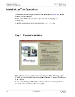
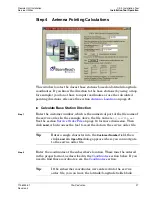
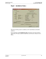
Step 1
Physical Installation
This window provides guidance for installing the BRU-150 components.
Use the pop-up windows from the
Click Here
buttons, or see the
Installation
Quick Guide
.
If you are installing a BRU-100, see the
Installation and Configuration
manual or the
Installation Summary
guide.