background image

13 / 32 

REV. 01


• 

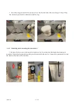
Insert the ring provided in the accessory box into the left side of the tire changer’s body. Place 

the container provided for lubricant inside the ring.


4.2.2   Mounting and connecting the manometer


• 

Remove the top screw and loosen the bottom screw from the plate that holds the manometer 

assembly. Mount the manometer assembly and fasten with both screws. Connect the pneumatic line into 
the union on the back of the machine. 


Summary of Contents for 70-030

Page 1: ...1 32 REV 01 70 030 Semi Automatic Tire Changer USER AND MAINTENANCE MANUAL THE CARTEK GROUP 6950 EAST N AVENUE KALAMAZOO MI 49048...

Page 2: ...Indicates the operations which need proper care Indicates prohibition Indicates a possibility of danger for the operators BOLD TYPE Important information WARNING before operating the unit and carrying...

Page 3: ...1 CONTENTS 1 INTRODUCTION 4 2 GENERAL INFORMATION 6 3 TRANSPORT UNPACKING AND STORAGE 9 4 INSTALLATION 10 5 OPERATION 21 6 INFLATING 25 7 MAINTENANCE 27 8 TROUBLESHOOTING 29 9 ELECTRIC AND PNEUMATIC D...

Page 4: ...his manual and that shown on the plate fixed to the tire changer the latter should be taken as correct Type Volt Amp Kw Ph Hz Year of manufacturing Air supply 8 10 bar 115 145 PSI 1 3 MANUAL KEEPING F...

Page 5: ...the above actions Removing or tampering with safety devices immediately invalidates the warranty TO THE READER Every effort has been made to ensure that the information contained in this manual is co...

Page 6: ...RER cannot be held responsible for any damage caused through the use of this tire changer for purposes other than those specified in this manual and therefore inappropriate incorrect and unreasonable...

Page 7: ...7 32 REV 01 2 3 DANGER WARNING SIGNS...

Page 8: ...h 470mm 18 5 Force on bead breaker blade 10 bar 2500 kg Working pressure 8 bar 116 psi Inflating pressure device max 3 5 bar 50 psi Power supply voltage 230V 1Ph 110V 1Ph Motor power 0 75KW 230V 1Ph s...

Page 9: ...ert the forks at the points shown in figure 3 3 2 UNPACKING Remove the protective cardboard and the nylon bag Check that the equipment is in perfect condition making sure that no parts are damaged or...

Page 10: ...d to the main electric power supply and the compressed air system It is therefore advisable to install the machine near the corresponding sources The place of installation must also provide at least t...

Page 11: ...ch Fig 5 a This operation must be performed by two operators A crane or similar equipment may be required to safely lift the vertical arm Proceed to screw in the knob that serves as a Stopper into the...

Page 12: ...the shop s air supply to the Quick connect adapter as shown below Fig 5 d Keep the air flow off until the machine is ready for operation Connect the hose coming out from the back of the machine into t...

Page 13: ...ontainer provided for lubricant inside the ring 4 2 2 Mounting and connecting the manometer Remove the top screw and loosen the bottom screw from the plate that holds the manometer assembly Mount the...

Page 14: ...t arm Lift by hand the mount demount arm and place a wedge wood etc to hold in place Remove the screw the holds the plastic cap and remove the cap completely Insert the spring provided in the accessor...

Page 15: ...machine Place cover aside to gain access to the inside of the machine Mount the side support of the assist arm onto the chassis of the tire changer right rear corner Fasten the 3 screws with a wrench...

Page 16: ...the assist arm from the bottom and fasten with 2 screws using a wrench Install the Assist arm Fasten the bolt on the assist arm support through the assist arm itself The hard plastic foot comes in mou...

Page 17: ...the valve inside the machine Splice the pneumatic hose coming out from the main valve assembly located inside the machine Splice the hose approximately 3 4 away from the valve as marked with a red arr...

Page 18: ...tion job must be carried out by professional and qualified personnel Make sure that the power supply is correct Make sure the connection of the phases is right Improper electrical hook up can damage t...

Page 19: ...pedal Z is pressed down the turntable Y should turn in a clockwise direction When pedal is pulled up the turntable should turn in an anticlockwise direction If the turntable turns in the opposite dir...

Page 20: ...middle range measure from 12 to 28 ext considering the rim outer side and from 14 30 int if you lock the rim from inner side It is however possible to change this dimension range in case of need when...

Page 21: ...of action can be pressed or crushed Check that the tire is deflated If not deflate it Close the turntable clamps completely Bead breaking with the clamps in open position can be extremely dangerous fo...

Page 22: ...clamps and press the pedal V to open the clamps and thereby lock the rim Make sure that the rim is rigidly fixed on the clamps Operator should never place hands in between wheel assembly and tire cha...

Page 23: ...oy rims internal micro cracks may not be visible to human eye This can compromise the rim and can also be a source of danger especially during inflation The diameter of the rim and tire are exactly th...

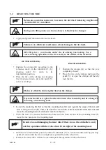
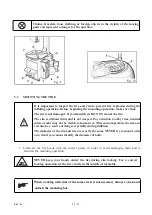
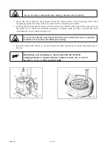
Page 24: ...on the pedal Z to rotate the turntable clockwise Continue until you have covered the entire circumference of the wheel rim Fig 12 To prevent accidents keep hands and other parts of the body as far as...

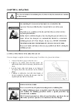
Page 25: ...INFLATING TIRE USING AIRLINE GAUGE This tire changer is supplied with an airline gauge To inflate a tire proceed as follows Connect the airline gauge to the tire valve Check to be certain that rim an...

Page 26: ...st the rim then press pedal all the way down C Fig 21 A strong a i r jet will be released through the nozzles in the slides and this will help the bead seal Release the tires set the pedal in the inte...

Page 27: ...laints deriving from the use of spare parts made by other manufacturers or for damage caused by tampering or removal of safety systems 7 2 MAINTENANCE OPERATIONS Clean the turntable once a week with d...

Page 28: ...ng clamps see Fig 18 and proceed as follows 1 Remove the left side panel of the machine body by unscrewing the four fixing screws 2 Unscrew the silencer installed on the pedal system behind the clamp...

Page 29: ...or close Silencer clogged Clean or replace silencer Turntable does not lock the wheel rim correctly Clamps worn Replace clamps Turntable cylinder s defective Replace cylinder gasket The tool touches t...

Page 30: ...CHAPTER 9 ELECTRIC AND PNEUMATIC DIAGRAM STANDARD ELECTRIC DIAGRAM...

Page 31: ...STANDARD PNEUMATIC SYSTEM DIAGRAM...

Page 32: ...NEUMATIC SYSTEM DIAGRAM 3 Safety Valve 10 Divider 4 Tank 11 Pressure gauge 5 Setting solenoid valve 12 Inflating unit 6 GT pedal valve 13 Deflating valve 8 Safety Valve 14 Rotation union 9 Inflating h...

Reviews: