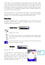
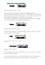
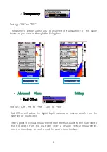
background image

22 


o


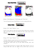
Sonar Chart Mode


Settings: “White Background”, “Blue Background”, “Gray Scale” 


You can change the Sonar Chart Mode to suit your viewing preferences. 


o


Surface Clarity 

 
Settings: “Off”, “High”, “Medium”, “Low” 


Surface Clarity adjusts the filter that removes surface clutter noise caused by 

algae and aeration. The lower the setting,  the more surface clutter will be 

displayed. 

o


Noise Rejection


Settings: “Off”, “High”, “Medium”, “Low” 


The Noise Rejection system built into the sonar unit that constantly evaluates 

the effects of boat speed, water conditions and interference. 

This automatic feature gives you the best display possible  under most 

conditions. 


If you have high noise levels, try using the “High” setting. However, if you are 

having trouble with noise, we suggest  that you take steps to find the 

Summary of Contents for BC202

Page 1: ...BC202 User manual...

Page 2: ...ROR BOOKMARK NOT DEFINED KEY FUNCTIONS 9 POWER ON OFF 9 DISPLAY VIEW ERROR BOOKMARK NOT DEFINED SONAR ZOOM VIEW ERROR BOOKMARK NOT DEFINED STOP CHART 13 SONAR VIEW ERROR BOOKMARK NOT DEFINED ACCESSING...

Page 3: ...sh or the depth of fish and other parameters for your reference How Does Sonar Work Sonar technology is based on sound waves The system uses sonar to locate and define the structure bottom contour and...

Page 4: ...Resolution 480 272 Back lighting White Power 3 6W 5 4W Main body waterproof IP4 Sonar Frequency 200KHZ 83KHZ Depth Range Max 0 6 73M 0 1M Depth Range Min 0 6 M Operating temperature 20 70 Operating v...

Page 5: ...Fish situation and depth alarm Kell offset Zoom in on display of bottom tracking Kell offset setting Automatic depth range Noise Rejection 100 level sensitivity setting Automatic and manual selection...

Page 6: ...5 Product List 1 Receiver 2 Transmitter 3 Receiver antenna 4 Transmitter antenna 5 Transmitter Power Cable 6 Battery Charger 7 Rechargeable Battery 8 pcs 8 Charger Power Cable 9 Sonar Transducer...

Page 7: ...6 Transmitter List 1 Transmitter power Cable 2 Transmitter 3 Sonar Transducer 4 Transmitter Antenna Receiver List 1 Receiver 2 Receiving antenna...

Page 8: ...7 Product port connection introduction Transmitter port 1 Power port 2 Snoar transducer port 3 Antenna Receiver port 1 Antenna pedestal 2 Receiver power input...

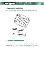
Page 9: ...ply mode Use 8 pcs AA batteries put 8 pcs AA batteries into the battery box Transmitter power supply mode The Transmitter is powered by 12V external power supply and the Transmitter Power Cable is con...

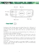
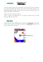
Page 10: ...seconds the screen will display Shutdown Stop Chart When the unit is working press the Power Key to stop the screen chart on the screen and press the key again to restore the screen chart Save setting...

Page 11: ...nal amplification press the EXIT key the system returns to the detection mode Sonar frequency conversion When the unit starts working you can press the EXIT key to switch between different frequencies...

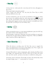
Page 12: ...ple options in the submenu press the up and down arrow keys successively to select the options that need to modify the setting value When the sonar signal is manually zoomed in you can move the zoom p...

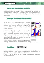
Page 13: ...e of the screen and the zoomed view is displayed on the left side of the screen In the Sonar Zoom View on the unzoomed display screen on the right there will be a zoomed preview box The contents of zo...

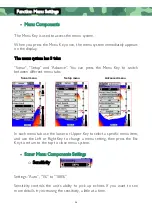
Page 14: ...point you cannot manually adjust the position of the zoom preview box There are 3 tabs in the menu system Sonar Setup and Advanced You can press the Menu Key to switch between different menu tabs Sto...

Page 15: ...ween different menu tabs In each menu tab use the lower or Upper Key to select a specific menu item and use the Left or Right Key to change a menu setting then press the Esc Key to return to the top t...

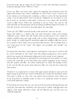
Page 16: ...t needs a sieve filters out unnecessary information The sensitivity here is the sieve pore of the sieve The higher the sensitivity the smaller the sieve pore Increasing the sensitivity is equivalent t...

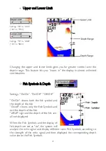
Page 17: ...to 0 80m Auto There are 8 setting values in this menu When the depth unit is set to FT feet the 8 setting values are 0 9FT 0 15FT 0 30FT 0 60FT 0 90FT 0 120FT 0 240FT Auto When the depth unit is set t...

Page 18: ...ttings On On On Off Off Off On On shows both the fish symbol and the depth of the fish On off shows only the Fish Symbols and not the depth of the fish off off sign and the depth of the fish are all n...

Page 19: ...to judge by the reflected sonar signal Please Note The sonar s microcomputer is sophisticated but it can be fooled It can t distinguish between fish and other suspended objects such as trotlines subm...

Page 20: ...finder is clear viewing in direct sunlight so the backlight can be turned off when used outdoors during the day o Volume Settings High Medium Low Volume setting allows you to adjust the Alarm Volume...

Page 21: ...ke a sound and the Depth Alarm Indicator will blink when the bottom signal goes shallower than the Depth Alarm s setting The Depth Alarm function is specially designed for Marine users Users can set t...

Page 22: ...Offset Settings Off 9ft to 9ft 3m to 3m Keel Offset will adjust the digital depth readout to indicate depth from the waterline or boat s keel Enter a positive vertical measurement from the transducer...

Page 23: ...ration The lower the setting the more surface clutter will be displayed o Noise Rejection Settings Off High Medium Low The Noise Rejection system built into the sonar unit that constantly evaluates th...

Page 24: ...time and then the display becomes black right away Black mesh in the middle area of the display after this you can continue doing the following steps 2 Transmitter then check the transmitter you will...

Reviews: