background image


BEAST BOX 1.0 BUILD GUIDE 


Summary of Contents for BEAST BOX 1.0

Page 1: ...BEAST BOX 1 0 BUILD GUIDE ...

Page 2: ...K 7 OK1 6N138 1 C1 60nf 100nf 1 C3 1nf 3 3nf 1 C2 10uf 1 C4 C11 C12 C17 100nf 4 C18 10uf 1 C20 100uf 1 L1 100uh 1 IC1 LD1117v33 1 IC2 dspic33fj128gp802 1 IC3 MCP602 MCP6022 1 Led1 3mm 1 Vactrol 1 SPST Switches 4 9mm Potentiometer 10K Linear taper 6 3 5mm mono socket 1 5 pin din socket 1 2 1mm socket 1 2 1mm to 9v battery clip 1 ...

Page 3: ...ip it over to solder Use a piece of card board or a book etc to hold them in place while flipping over Solder one pin from each strip flip over and make sure they are sitting evenly You can melt the pin with the soldering iron to adjust Once happy they are seated correctly solder the rest of the pins in place ...

Page 4: ...2 Install D2 1n4004 power diode into D2 and solder in place Make sure the silver band on the diode matches the band on the PCB ...

Page 5: ...3 Install D1 and D3 1N4148 signal diode into D1 and D3 then solder in place Again making sure the black band on the diode matches the band on the PCB ...

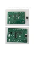
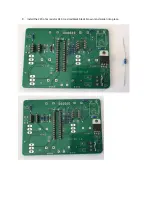
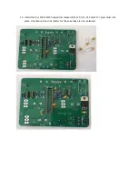
Page 6: ...4 Install IC1 the LD1117v33 voltage regulator and solder into place ...

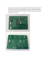
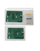
Page 7: ...5 Install the seven 10K resistors R18 R23 R24 R25 R26 R27 and R30 and solder into place ...

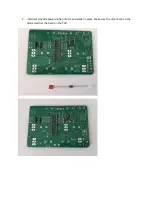
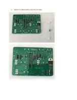
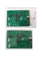
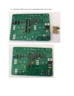
Page 8: ...6 Install L1 the 100uh inductor and solder into place ...

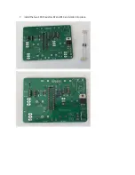
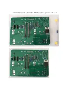
Page 9: ...7 Install the two 100R resistors R2 and R13 and solder into place ...

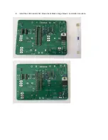
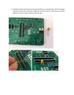
Page 10: ...8 Install the 100K resistor R3 brown black black orange brown and solder into place ...

Page 11: ...9 Install the 220 ohm resistor R10 red red black black brown and solder into place ...

Page 12: ...10 Install the 4 7K resistor R11 yellow violet black brown brown and solder into place ...

Page 13: ...11 Install the 1K resistor R12 brown black black brown brown and solder into place ...

Page 14: ...ntalum capacitor paying close attention to the orientation NOTE The longer leg is the positive lead and must be installed into the hole marked C2 Double check orientation against the pictures and when happy solder into place ...

Page 15: ...13 Install the four 100nf MLCC capacitors marked 104 C4 C11 C12 and C17 and solder into place Orientation does not matter for these as they are non polarized ...

Page 16: ...14 Install the 82nf MKT capacitor C1 marked 823K100 and solder into place ...

Page 17: ...15 Install the 2 7nf MKT capacitor C3 marked 272K100 and solder into place ...

Page 18: ...16 Install the 100uf electrolytic capacitor C20 these capacitors are polarized and must be installed with the longer lead into the hole marked with the symbol ...

Page 19: ...17 Install the 10uf electrolytic capacitor C18 these capacitors are polarized and must be installed with the longer lead into the hole marked with the symbol ...

Page 20: ...18 Install Led1 leds are polarized and must be installed with the longer lead into the hole marked with a symbol and the shorter leg into the hole marked with the symbol ...

Page 21: ...th the shorter legs Because LEDs are polarity sensitive polarized it must be installed in the correct direction Locate the white dot on the side of the vactrol this is the negative pin on the LED inside the vactrol The negative pin marked with the dot must go into the hole marked with the word DOT Refer to pictures When happy that its installed correctly solder it into place ...

Page 22: ...ers refer to picture below This is required so that the switches fit Note the switches will be a tight fit even when bent this is because the switches will hold the PCB board in place and must be very snug It might take a minute or two to push them into place be patient they don t need to be flush with the PCB board Refer to the pictures below DO NOT SOLDER THEM YET ...

Page 23: ... on the PCB gently push them into the aluminum box 23 Now place the plastic over the top and give the switches and pots a bit of a wiggle to get them through and everything seated nicely When you are happy take 4 of the nuts from the switches and tighten them with your fingers as tight as you can ...

Page 24: ...24 Gently flip the box back over and solder the switches and potentiometers into place ...

Page 25: ...of pliers 26 In the pictures above the white wire is the audio ground wire and the blue wire is the audio output As per the picture below solder the audio out wire to the pad marked A OUT and the audio ground wire to the pad marked A GND Push the 3 5mm socket through the middle hole remember the middle lug must be removed from the socket so it doesn t touch the PCB board Put the knurled nut onto t...

Page 26: ...ect the power socket Cut and strip a piece of red wire and a piece of black wire Solder them onto the socket as per the pictures below the third lug on the socket is not used and should be cut off with a pair of side cutters ...

Page 27: ... place the red wire goes to the pad marked VCC and the black wire goes to the pad marked GND as per the photos below Solder the wires in place 29 Push the socket through the hole place the split washer on then tighten the nut ...

Page 28: ...h the hole in the box then gently bend the unused lugs out of the way as per the second photo below Now take two M3 screws and M3 nuts and attach the midi socket to the box Once the midi socket is attached solder the two wires onto the pads marked M5 and M4 orientation matters so use the color of the wire in the pictures below to determine which wire goes to which pad ...

Page 29: ...IC2 IC3 and OK1 IC s must be installed in the correct direction There is either a dot or a notch on the IC to indicate pin 1 There is also a notch on the PCB silkscreen to indicate pin 1 Make sure the notch dot on the IC package matches the silkscreen on the PCB ...

Page 30: ...32 Flip the box over and install the knobs Turn the potentiomenters fully counter clock wise then loosen the grub screw on the knob place on the potentiometer and tighten as per the photos below ...

Page 31: ...nstalled the wrong way around Midi is working but there is no audio check the wires on the audio socket maybe you have them around the wrong way If its still not working check the wires AGAIN Check that all IC s are the right way around If its still not working remove the knobs and remove the nuts from the switches so the PCB can come out Double check the PCB for dry joints Look for things that yo...

Reviews: